Nordson_EFD_P-Jet_SolderPlus_Operating_Manual.pdf - 第22页
Liquidyn P-Jet SolderPlus Jet Valve 22 www.nordsonefd.com info@nordsonefd.com +1-401-431-7000 Sales and service of Nordson EFD dispensing systems are available worldwide. Connect Cables Connect the M8 valve cable and oth…
Liquidyn P-Jet SolderPlus Jet Valve
21www.nordsonefd.com info@nordsonefd.com +1-401-431-7000 Sales and service of Nordson EFD dispensing systems are available worldwide.
Mount the Valve
Mount the valve using either of the following options.
Standard Mounting
Secure the valve using two M3 x 25 hex screws (customer-supplied).
Four mounting holes are available to allow for adjustment.
Quick-Mounting
An optional quick-mounting bracket is available for faster valve
removal and installation. Once the valve is installed using the quick-
mounting components, it can be easily removed or installed using
the quick-release fastener. Refer to “Quick-Release Valve Mounting
Components” on page38 for the quick-mounting kit part number.
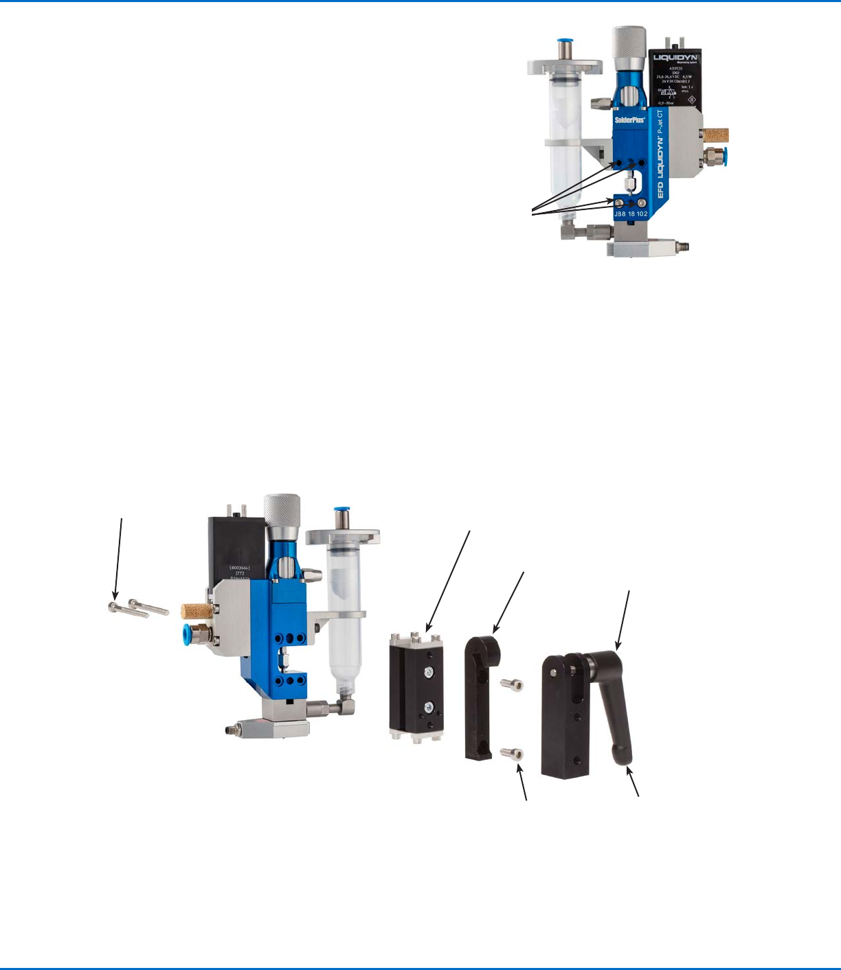
You will need the following items:
• Vibration decoupler
• Quick-release fastener
• 2 M4 hex screws (minimum length: 10 mm)
• Hex wrench, size 2.5
• Hex wrench, size 3.0
Example of the quick-release mounting option
M3 x 30
mounting
screws
Vibration decoupler
Quick-release fastener
Hook (hooks into the
quick-release fastener)
M4 x 30 mounting
screws (for mounting
onto a socket; not
included)
Lever (secures the hook)
M3 mounting
hole locations
Liquidyn P-Jet SolderPlus Jet Valve
22 www.nordsonefd.com info@nordsonefd.com +1-401-431-7000 Sales and service of Nordson EFD dispensing systems are available worldwide.
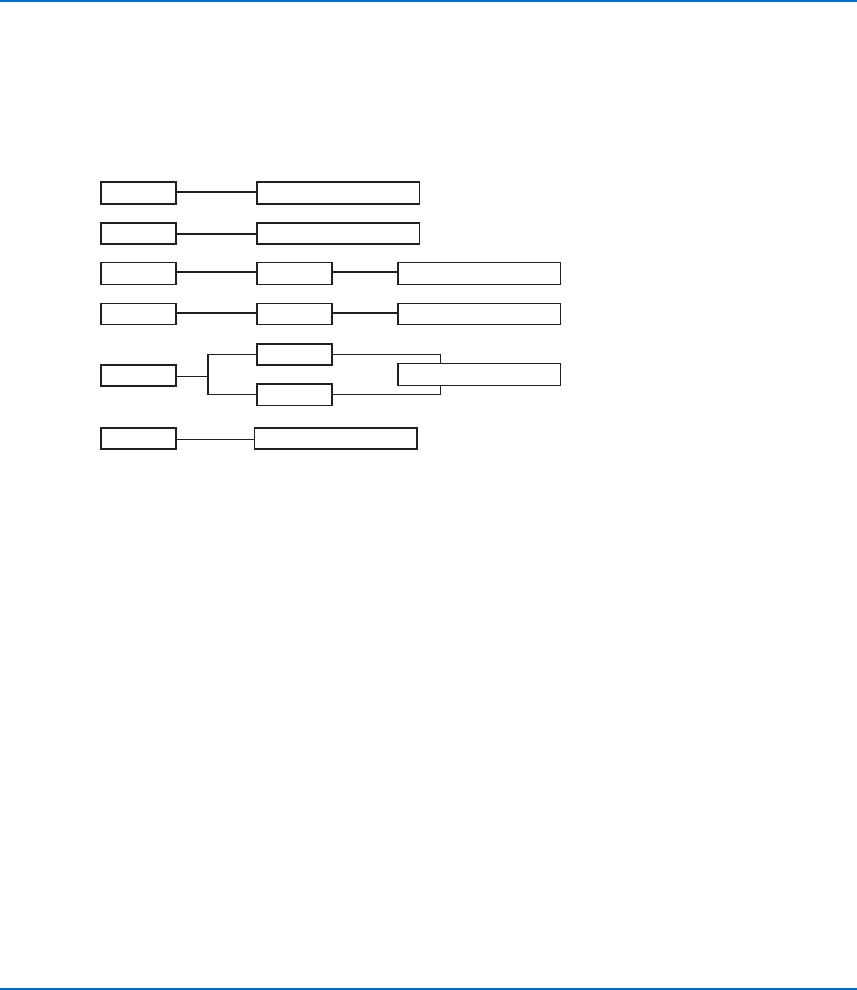
Connect Cables
Connect the M8 valve cable and other communication cables as applicable for your system to control the operation
of the valve. The diagram below shows some typical system control setups.
NOTE: The valve is triggered by a square-wave signal (24 VDC). The length of the pulse from the control signal
defines the opening time of the valve and can be set from 2 ms to infinity. Most PLC systems make use of high
performance transistor outputs which are suitable to control the valve directly. The valve is electrically connected to
the control system via the supplied M8 valve cable.
V10
V200
PLC
PLC
PLC
P-Jet SolderPlus
V10
V200
V10
T10
PLC
P-Jet SolderPlus
P-Jet SolderPlus
P-Jet SolderPlus
P-Jet SolderPlus
P-Jet SolderPlus
Key:
T10 = Liquidyn T10 or T20 heater controller
V10 = Liquidyn V10, V10M, V10D, or M10D controller
V200 = Liquidyn V200 controller
PLC = Higher-level controller
Liquidyn P-Jet SolderPlus Jet Valve
23www.nordsonefd.com info@nordsonefd.com +1-401-431-7000 Sales and service of Nordson EFD dispensing systems are available worldwide.
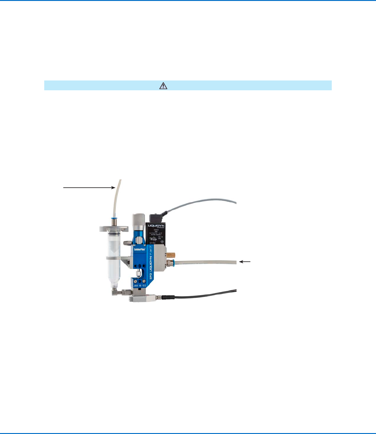
Connect the Air Supply
To achieve consistent dispensing results, the process parameters must be kept constant. The valve has two air
pressure connections (operating pressure and fluid pressure) which must be continuously supplied with air pressure.
The level of pressure depends on the respective process. Each valve must be separately connected to a continuous
air supply adjustable through a precision pressure regulator. To keep the operating pressure stable and constant,
use a pneumatic accumulator (at least 0.4 liter volume).
For an air supply connection diagram, refer to “Installation Example” on page24.
CAUTION
Ensure that the pressure limit values for the syringe barrel and air pressure tubing are not exceeded.
1. For the operating pressure, connect 6 mm OD tubing to the plug-in connector on the side of the valve.
2. For the fluid pressure, connect 4 mm or 6 mm tubing to the syringe barrel adapter.
NOTE: Nordson EFD recommends installing a precision pressure regulator with a maximum control tolerance of
0.2%.
Air input (operating
pressure)
Air input
(fluid pressure)