Nordson_EFD_P-Jet_SolderPlus_Operating_Manual.pdf - 第28页
Liquidyn P-Jet SolderPlus Jet Valve 28 www.nordsonefd.com info@nordsonefd.com +1-401-431-7000 Sales and service of Nordson EFD dispensing systems are available worldwide. T appet Adjustment The valve is equipped with two…
Liquidyn P-Jet SolderPlus Jet Valve
27www.nordsonefd.com info@nordsonefd.com +1-401-431-7000 Sales and service of Nordson EFD dispensing systems are available worldwide.
Parameter Settings (continued)
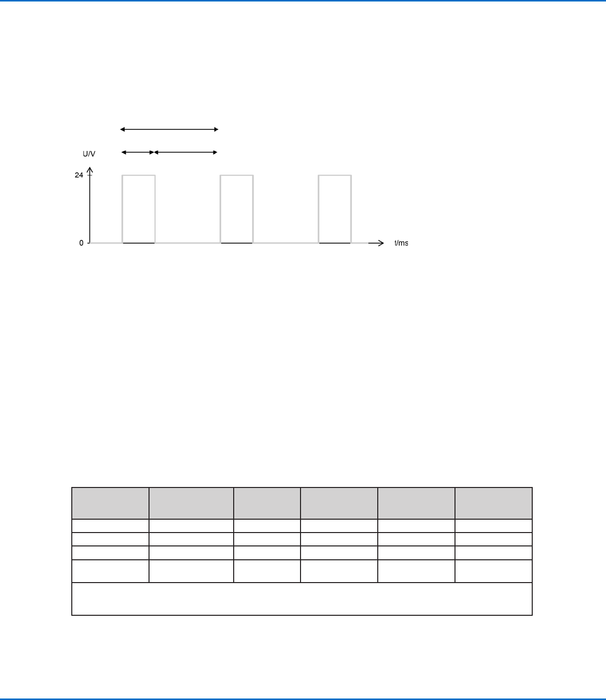
Frequency (continued)
EXAMPLE:
• To achieve 50Hz with a 2 ms Pulse Time, set the pause time to 18 ms.
• To achieve 50Hz with a 10 ms Pulse Time, set the pause time to 10 ms.
Pulse time Pause time
Dispensing cycle
Fluid Pressure
The fluid pressure must be properly set to ensure that material is supplied at a consistent volume. Consider the
following when setting the fluid pressure:
• The fluid pressure must stay within the tubing pressure specifications.
• Fluid supply tubing must be resistant to chemicals.
• The fluid pressure must be high enough for the material to exit the nozzle opening.
• The required fluid pressure will vary depending on the material, its viscosity, and the ambient temperature.
• Decreasing the fluid pressure too much may, in extreme cases, prevent proper deposit separation from the
nozzle.
• Prevent pressure fluctuations. Note that pressure loss due to friction occurs as material flows through the
material delivery components.
Recommended Setup Adjustments
The following table provides recommended adjustments to help you quickly find optimum system settings
for your application. Because of the diversity in materials that can be dispensed, the effectiveness of these
recommendations can vary, but they serve to share our experience with you.
Goal Operating Pressure
Tappet
Force Screw
Adjustment
Fluid Pressure
Heater
(Temperature)
Nozzle Orifice
Diameter
Smaller dots Not applicable Down Down Down Down
Bigger dots Not applicable Up Up Up Up
Prevent satellites Down Up Down Down Up
Prevent residue at
the nozzle
Up Down Down Up Not applicable
Key:
Down = lower operating pressure or temperature / tighten screw / smaller diameter
Up = greater operating pressure or temperature / loosen screw / larger diameter
Liquidyn P-Jet SolderPlus Jet Valve
28 www.nordsonefd.com info@nordsonefd.com +1-401-431-7000 Sales and service of Nordson EFD dispensing systems are available worldwide.
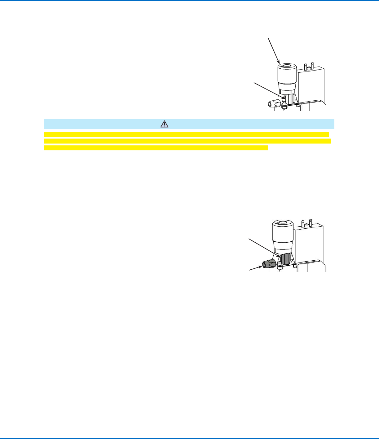
Tappet Adjustment
The valve is equipped with two mechanisms for tappet
adjustment:
• Force screw (non-slip knurled screw) — sets the dynamic
of the tappet movement.
• Stroke adjustment knob (fine diamond knurl screw) —
sets the tappet stroke.
The factory settings for both mechanisms are appropriate for
most applications. However, depending on the dispensing
task and on the material, each can be adjusted to fine-tune the
dispensing result.
CAUTION
When dispensing solder paste, do not adjust the tappet of a wetted and closed valve. Doing so can grind material
into the nozzle, causing nozzle clogging and other related problems. Refer to “Appendix C, Special Instructions for
Solder Paste Dispensing” on page47 for steps that apply only to solder paste dispensing.
Adjusting the Force Screw
Adjust the raster element (see NOTE below) and then turn the force screw clockwise (as seen from an aerial view)
to change the dynamic of the tappet movement. In most cases, simultaneously increasing the operating pressure is
helpful.
NOTE: Use the spring-loaded raster element as follows:
• Completely loosen the element to turn the force
screw.
• Half-tighten the element to hear a clicking sound
when you turn the force screw.
• Completely tighten the element to secure the force
screw.
To return the force screw to the factory setting:
1. Completely loosen the raster element.
2. Turn the force screw counterclockwise until it stops.
3. Turn the force screw clockwise for 25 clicks (15 clicks = one full turn).
4. Completely tighten the raster element to secure the force screw.
Stroke adjustment
knob
Force screw
Force screw
Spring-loaded
raster element
Liquidyn P-Jet SolderPlus Jet Valve
29www.nordsonefd.com info@nordsonefd.com +1-401-431-7000 Sales and service of Nordson EFD dispensing systems are available worldwide.
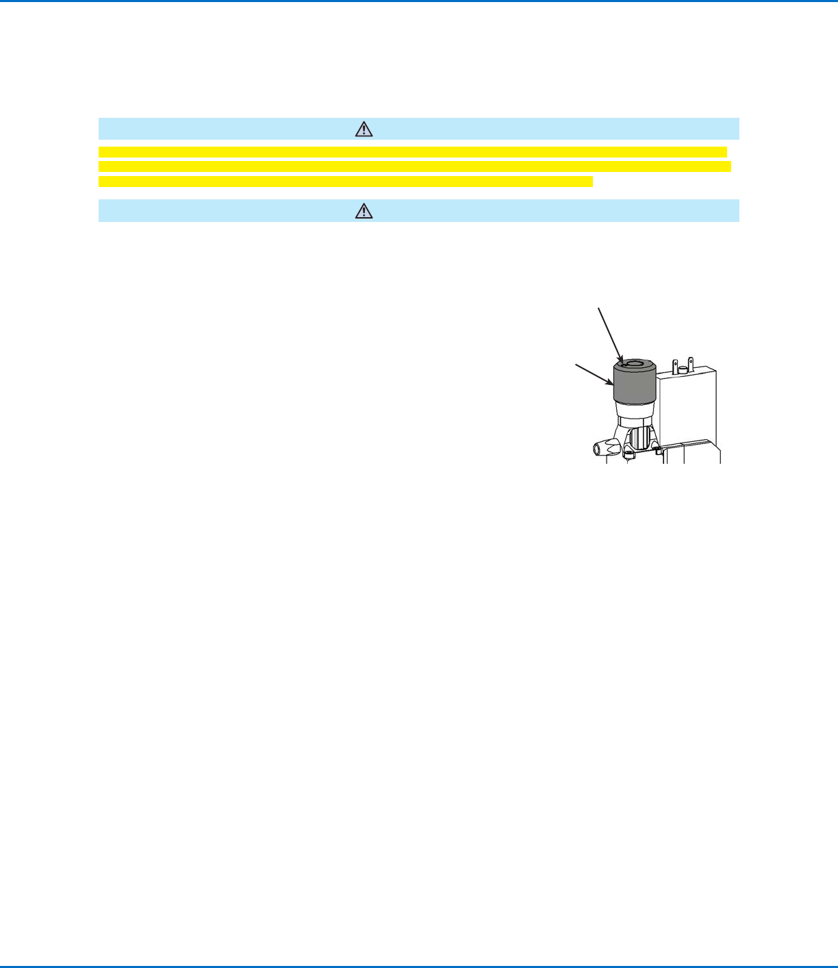
Adjusting the Stroke
CAUTION
When dispensing solder paste, do not adjust the tappet of a wetted and closed valve. Doing so can grind material
into the nozzle, causing nozzle clogging and other related problems. Refer to “Appendix C, Special Instructions for
Solder Paste Dispensing” on page47 for steps that apply only to solder paste dispensing.
CAUTION
Do not keep turning the stroke adjustment knob after you feel the torque elevate. Doing so can damage the valve.
1. Use a hex wrench to loosen the locking set screw.
2. Turn the stroke adjustment knob clockwise (as seen from an aerial view) to reduce the stroke.
3. Tighten the locking set screw to secure the knob.
Torque: 0.3 N•m (2.7 in.-lb) maximum
NOTE: For very fine adjustment of the tappet stroke, loosen the
locking screw 2 turns, turn the stroke adjustment knob + 90° / - 90°
from its factory position, and observe the deposit cut-off or shape.
When the desired dispensing result is achieved, tighten the locking
screw. Note that in this situation the maintenance intervals described
under “Service” on page30 will need to be adapted depending on
the dispensed material and on the stroke.
Locking set screw
Stroke adjustment
knob
To return the stroke adjustment knob to the factory setting:
1. Loosen the locking set screw.
2. Turn the stroke adjustment knob clockwise (as seen from an aerial view) until
the stroke stop lies flat against the valve tappet. This can be felt when the
torque elevates.
3. Turn the knob 270° counterclockwise.
4. Tighten the locking set screw to prevent accidental turning of the knob.
Torque: 0.3 N•m (2.7 in.-lb) maximum
Tappet Adjustment (continued)