Nordson_EFD_P-Jet_SolderPlus_Operating_Manual.pdf - 第46页
Liquidyn P-Jet SolderPlus Jet Valve 46 www.nordsonefd.com info@nordsonefd.com +1-401-431-7000 Sales and service of Nordson EFD dispensing systems are available worldwide. Pneumatic Contr ol To achieve consistent dispensi…
Liquidyn P-Jet SolderPlus Jet Valve
45www.nordsonefd.com info@nordsonefd.com +1-401-431-7000 Sales and service of Nordson EFD dispensing systems are available worldwide.
Optional Nozzle Heater Control
A nozzle heater can be installed on the valve in place of the retaining nut. The heater can be controlled using a
separate temperature controller (such as the Liquidyn T10) or by the Liquidyn V200 controller.
To use another method for controlling the heater, the following information applies:
• The heater comprises a heating coil and a 100-ohm platinum (PT100) resistance temperature detector (RTD).
• The heater can be triggered by most control units.
• Heater power consumption is approximately 1.3 Amps, with 24 VDC used during the heating process.
NOTE: The maximum heater temperature is 90° C (194° F). For consistent dispensing results, keep the control
deviation to a minimum (lower than 3%).
Nozzle Heater Specifications
Item Specification
Input voltage 24 VDC
Maximum power consumption 1.3 Amp
Maximum nozzle heater temperature 90° C (194° F)
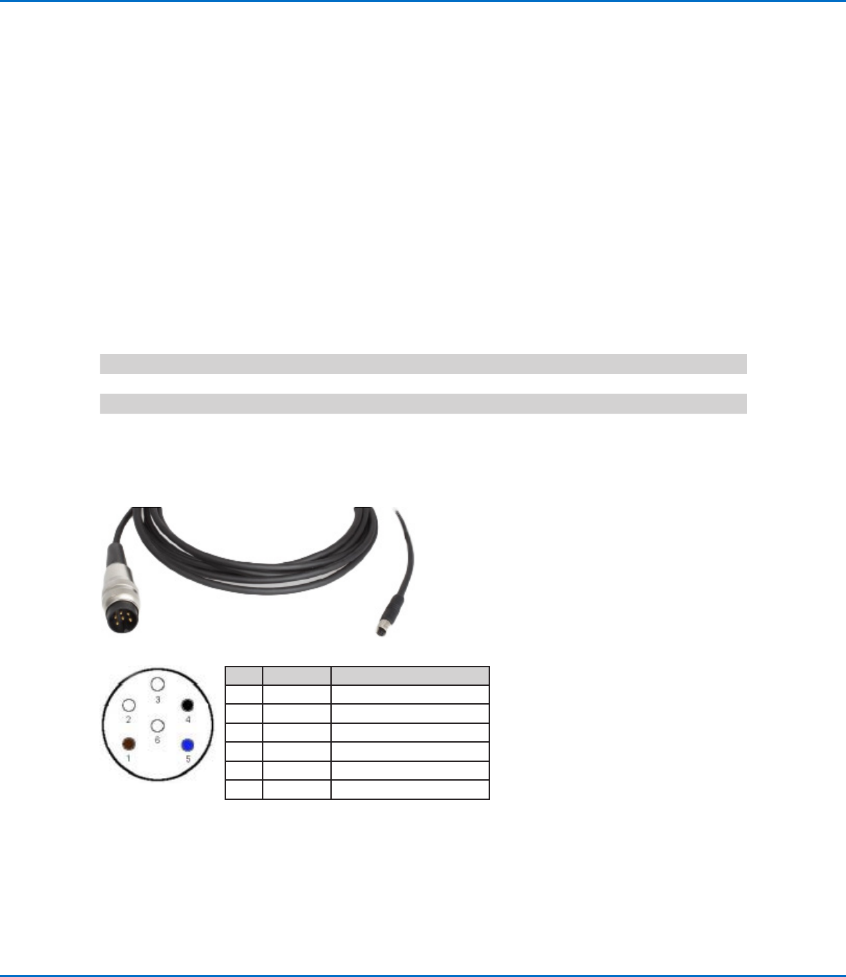
Nozzle Heater Cable Pin Positions
Pin Color Function
1 Brown Heating coil
2 White Heating coil
3 White Not assigned
4 Black PT100 RTD
5 Blue PT100 RTD
6 White Not assigned
6-pin plug
M5 plug
Appendix B, P-Jet SolderPlus Valve Interface Overview
(continued)

Liquidyn P-Jet SolderPlus Jet Valve
46 www.nordsonefd.com info@nordsonefd.com +1-401-431-7000 Sales and service of Nordson EFD dispensing systems are available worldwide.
Pneumatic Control
To achieve consistent dispensing results, the process parameters must be kept constant. The valve has two air
pressure connections (operating pressure and fluid pressure) which must be continuously supplied with air pressure.
The level of pressure depends on the respective process. Each valve must be separately connected to a continuous
air supply adjustable through a precision pressure regulator. To keep the operating pressure stable and constant,
use a pneumatic accumulator (at least 0.4 liter volume).
Appendix B, P-Jet SolderPlus Valve Interface Overview
(continued)
Operating Pressure Specification
For the operating pressure, connect 6 mm OD tubing to the plug-in connector on the side of the valve.
Item Specification
Input air pressure 3–8 bar (44–116 psi)
Fluid Pressure Specifications
For the fluid pressure, connect 4 mm or 6 mm tubing to the syringe barrel adapter (syringe barrel installations only)
Item Specification
Fluid pressure range 0.1–4.1 bar (1.5–60 psi)
Maximum fluid pressure 100 bar (1450 psi)
CAUTION
Ensure that the pressure limit values for the syringe barrel and air pressure tubing are not exceeded.
NOTE: Nordson EFD recommends installing a precision pressure regulator with a maximum control tolerance of
0.2%.
Valve Configuration Options
• The fluid body can be mounted in other 90-degree positions.
• The operating air pressure connector can be mounted on the opposite side of the valve.
• Standard cartridge centering is 10 cm
2
(1.6"
2
); 30 cm
2
(4.7"
2
) can be supplied upon request.
• The valve can be supplied without cartridge centering, in which case a tubing connector is mounted on the valve.
• The material to be dispensed can be supplied through tubing instead of through a syringe barrel. This tubing is
connected to the valve using an M8 x 1 cap nut.

Liquidyn P-Jet SolderPlus Jet Valve
47www.nordsonefd.com info@nordsonefd.com +1-401-431-7000 Sales and service of Nordson EFD dispensing systems are available worldwide.
Appendix C, Special Instructions for Solder Paste
Dispensing
This appendix provides startup, operating, and service instructions that are unique to solder paste dispensing using
the P-Jet SolderPlus valve. These instructions are cross-referenced at the applicable locations within this manual.
To Bring Solder Paste into the Nozzle at Initial Startup
Before the initial dispensing of solder paste, material must be introduced into the nozzle.
1. Begin with the following system settings:
Pulse Time 1 s (equivalent to 1000 ms + frequency >1Hz)
Fluid pressure (P1) 2 bar (30 psi)
Operating pressure (P2) 6 bar (87 psi)
Tappet force screw 55 N (33–35 clicks)
Tappet stroke 270°
Nozzle heater temperature 38–40° C (100–104° F)
2. Initiate a signal to the valve.
3. When solder paste flows out of the nozzle, stop the signal to the valve.
To Adjust the Tappet in a Solder Paste Dispensing Application
CAUTION
Do not adjust the tappet of a wetted and closed valve. Doing so can grind material into the nozzle, causing nozzle
clogging and other problems.
To properly adjust the tappet of a valve used in a solder paste dispensing application, supply a constant signal to
the valve to lift the tappet, then adjust the force screw or stroke. Refer to “Tappet Adjustment” on page28 for
detailed procedures.
Settings for Constant Dispensing of Solder Paste (Routine Operation)
Use the following settings for the constant dispensing of solder paste during routine operation of the solder paste
system:
Pulse Time 6 ms
Frequency 25Hz
Fluid pressure (P1) 2 bar (30 psi)
Operating pressure (P2) 6 bar (87 psi)
Tappet force screw 55 N (33–35 clicks)
Tappet stroke 270°
Nozzle heater temperature 38–40° C (100–104° F)