Nordson_EFD_P-Jet_SolderPlus_Operating_Manual.pdf - 第24页
Liquidyn P-Jet SolderPlus Jet Valve 24 www.nordsonefd.com info@nordsonefd.com +1-401-431-7000 Sales and service of Nordson EFD dispensing systems are available worldwide. Installation Example Item Description Pneumatic c…
Liquidyn P-Jet SolderPlus Jet Valve
23www.nordsonefd.com info@nordsonefd.com +1-401-431-7000 Sales and service of Nordson EFD dispensing systems are available worldwide.
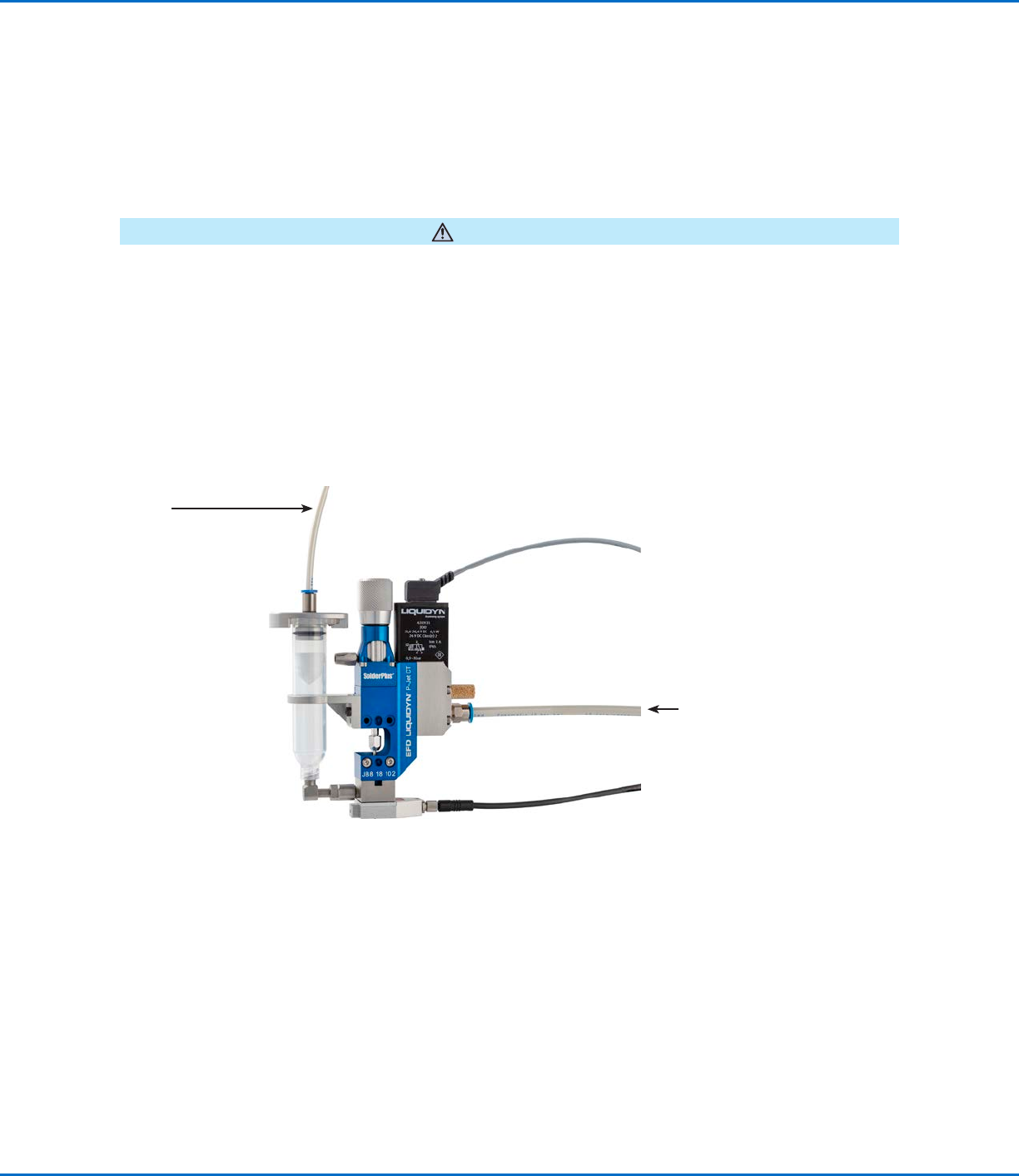
Connect the Air Supply
To achieve consistent dispensing results, the process parameters must be kept constant. The valve has two air
pressure connections (operating pressure and fluid pressure) which must be continuously supplied with air pressure.
The level of pressure depends on the respective process. Each valve must be separately connected to a continuous
air supply adjustable through a precision pressure regulator. To keep the operating pressure stable and constant,
use a pneumatic accumulator (at least 0.4 liter volume).
For an air supply connection diagram, refer to “Installation Example” on page24.
CAUTION
Ensure that the pressure limit values for the syringe barrel and air pressure tubing are not exceeded.
1. For the operating pressure, connect 6 mm OD tubing to the plug-in connector on the side of the valve.
2. For the fluid pressure, connect 4 mm or 6 mm tubing to the syringe barrel adapter.
NOTE: Nordson EFD recommends installing a precision pressure regulator with a maximum control tolerance of
0.2%.
Air input (operating
pressure)
Air input
(fluid pressure)
Liquidyn P-Jet SolderPlus Jet Valve
24 www.nordsonefd.com info@nordsonefd.com +1-401-431-7000 Sales and service of Nordson EFD dispensing systems are available worldwide.
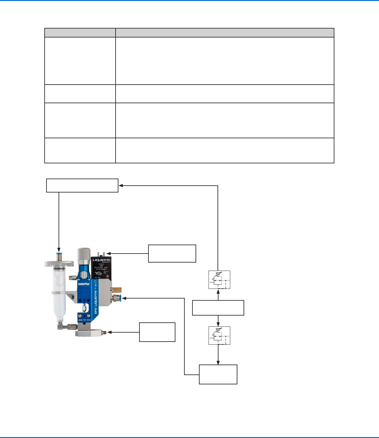
Installation Example
Item Description
Pneumatic connections
• Compressed air tube, 6 mm OD
• Dry, filtered air pressure, oil-free
• Filter grade: 40 µm
• Regulated by a precision pressure regulator
• Operating pressure limit: 3–8 bar (44–116 psi)
Fluid connection
• Syringe barrel accessories with compressed 4 mm air tubing
• Fluid pressure limit: 100 bar (1450 psi)
Electrical connections
• Supplied M8 valve cable from the valve to a Liquidyn valve controller or a higher-
level controller, such as a PLC
• Power supply: 24 VDC
• Power consumption: 0.5 Amp (peak 5.0 Amp)
Optional
• Nozzle heater (controlled by a temperature control unit)
• Process equipment (such as a laser light barrier for dot recognition or a cleaning
station for nozzles)
Liquidyn P-Jet SolderPlus valve connection diagram
Syringe barrel connection
Higher-level controller
(e.g., PLC)
Valve cable
4 mm air supply tubing
Fluid pressure
Precision
pressure
regulator
Precision
pressure
regulator
Air pressure source
Pressure
accumulator
(at least 0.4 liter)
Operating pressure
6 mm air supply tubing
P-Jet
SolderPlus
Temperature
controller (e.g.,
V200, T10)
Nozzle heater
cable
Liquidyn P-Jet SolderPlus Jet Valve
25www.nordsonefd.com info@nordsonefd.com +1-401-431-7000 Sales and service of Nordson EFD dispensing systems are available worldwide.
Initial Startup
This section provides recommendations for system startup and operation. System startup for the valve depends on
the control unit. If you are using a Nordson EFD Liquidyn valve controller, obtain the controller manual. If you are
using higher-level controller, the control is set up by the customer.
CAUTION
Before switching on the system, ensure that all electrical and pneumatic connections are connected correctly and
fully functioning.
1. Check electrical and pneumatic connections.
2. Switch on the control unit.
3. Turn on the air supplies.
4. (Solder paste applications only) If using the P-Jet SolderPlus valve in a solder paste dispensing
application, refer to “Appendix C, Special Instructions for Solder Paste Dispensing” on page47 for
steps that apply only to solder paste dispensing.
5. (All applications except solder paste applications) Use the following actions to set up and test the valve
operation using the control system manual or the customer-supplied control system and documentation. Refer
to “Parameter Settings” on page26 for information and recommendations on system setup.
a. Trigger the valve until the material to be dispensed leaves the nozzle opening. Place a collecting container or
paper sheet underneath the valve.
b. Clean the nozzle tip with a lint-free cloth.
c. Set the distance between the nozzle and the target (such as a sample product).
d. Initiate several dispense cycles to test the valve operation.
e. Evaluate the dispensing results and make adjustments until the desired dispensing performance is achieved.
Refer to “Parameter Settings” on page26 and to “Recommended Setup Adjustments” on page27 for
detailed information on system setup and adjustment.
6. To ensure optimal valve performance, maintain the system as described under “Service” on page30.