Nordson_EFD_P-Jet_SolderPlus_Operating_Manual.pdf - 第20页
Liquidyn P-Jet SolderPlus Jet Valve 20 www.nordsonefd.com info@nordsonefd.com +1-401-431-7000 Sales and service of Nordson EFD dispensing systems are available worldwide. Install a Nozzle Heater (Optional) The nozzle hea…
Liquidyn P-Jet SolderPlus Jet Valve
19www.nordsonefd.com info@nordsonefd.com +1-401-431-7000 Sales and service of Nordson EFD dispensing systems are available worldwide.
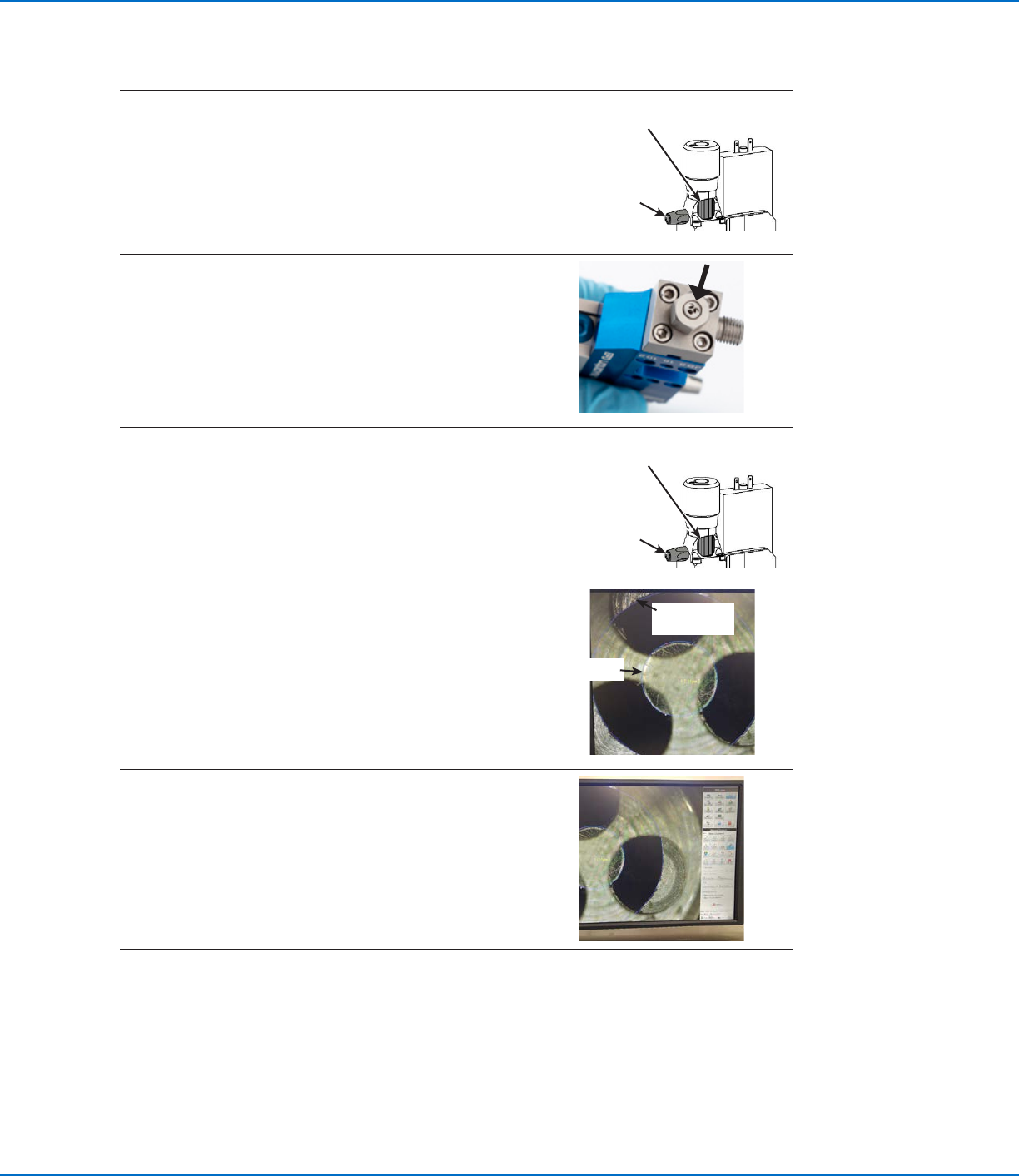
2. If you have not already done so, turn the force screw fully
counterclockwise as follows (to eliminate any spring force
on the tappet):
• Completely loosen the raster element.
• Turn the force screw counterclockwise until it stops.
• Completely tighten the raster element to secure the force
screw.
Force
screw
Raster
element
3. • Remove the nozzle, if present.
• Install the concentricity tool onto the fluid body where the
nozzle would mount.
• Install the nozzle retaining nut to secure the concentricity
tool.
4. • Turn the force screw one (1) click counterclockwise so
that there is a low spring force pushing the tappet onto
the concentricity tool.
Force
screw
Raster
element
5. • Place the valve upright under a measuring system (such
as a digital microscope with measurement capability).
• Adjust the magnification to 100 times (100x) and focus on
the flat surface of the tappet, which is at the same height
as the concentricity tool.
Tappet
Concentricity
tool
6. • Use the measuring system’s center-to-center tool to
measure the concentricity of the tappet to the inside ring
of the concentricity tool.
NOTE: The three holes in the concentricity tool act as
windows to view the inner diameter.
7. • Repeat the concentricity measurement three times
by repeating steps 1–6 (including turning the stroke
adjustment knob back when removing / installing the
concentricity tool).
• Average all three measurements. An acceptable tappet
concentricity is <75 µm.
Set the Tappet Concentricity (continued)
Liquidyn P-Jet SolderPlus Jet Valve
20 www.nordsonefd.com info@nordsonefd.com +1-401-431-7000 Sales and service of Nordson EFD dispensing systems are available worldwide.
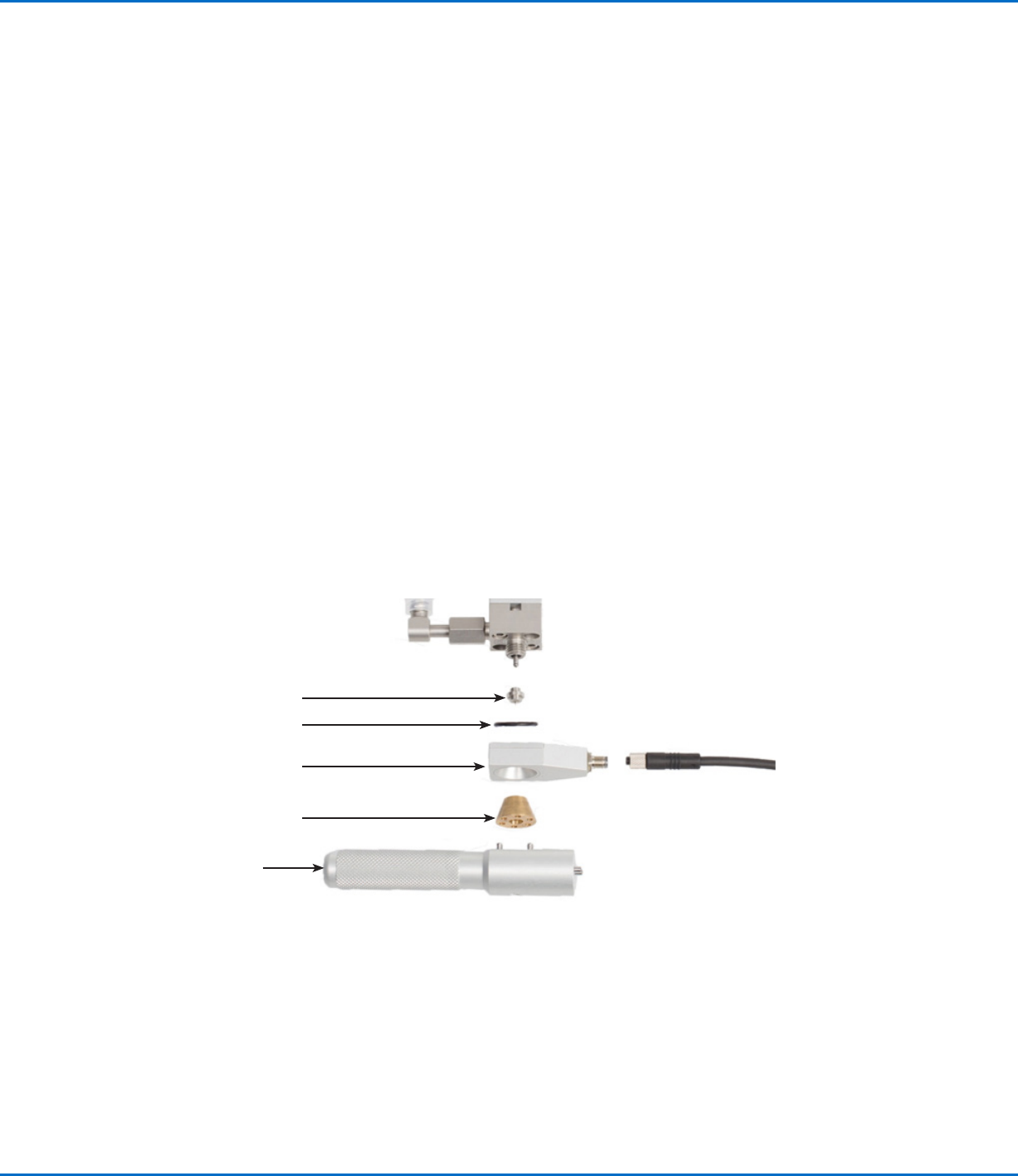
Install a Nozzle Heater (Optional)
The nozzle heater is an optional component; however, because most solder applications require a nozzle heater,
it was included as a step under “Assemble the Valve (Initial Assembly)” on page15. This section is included for
additional reference as needed.
The illustration below shows the installation of a nozzle heater. A nozzle heater controls the temperature of the
material in the nozzle. The nozzle is secured minimally by the nozzle heater with an elastomer (heater O-ring)
between it and the valve. The nozzle is fully secured by the retaining nut.
You will need the following items:
• Nozzle
• Nozzle heater
• Nozzle heater O-ring (NBR or EPDM)
• Retaining nut
• Heater key
• Heater cable
Refer to “Nozzle Heaters” on page39 for component part numbers.
NOTES:
• The nozzle retaining nut predominantly secures and seals the nozzle in place. The heater remains in contact with
the retaining nut through pressure supplied by a heater O-ring, which creates a partial space between the heater
and the fluid body. This ensures thermal contact and allows the heater to rotate slightly even when the retaining
nut is fully tightened.
• The image below is based on a Liquidyn P-Jet valve with a standard nozzle heater. The mounting process is the
same for all valves.
NOTES:
• The electrical connection for the
heater is supplied through the
provided heater cable.
• To attach or release the heater
cable, loosen or tighten the knurled
nut by hand. Be sure to connect
the heater cable plug in the correct
orientation.
Nozzle
Nozzle heater O-ring
Nozzle heater
Nozzle retaining nut
Heater key
Torque for a steel nozzle: 1.2 N•m (10.6 in.-lb)
Liquidyn P-Jet SolderPlus Jet Valve
21www.nordsonefd.com info@nordsonefd.com +1-401-431-7000 Sales and service of Nordson EFD dispensing systems are available worldwide.
Mount the Valve
Mount the valve using either of the following options.
Standard Mounting
Secure the valve using two M3 x 25 hex screws (customer-supplied).
Four mounting holes are available to allow for adjustment.
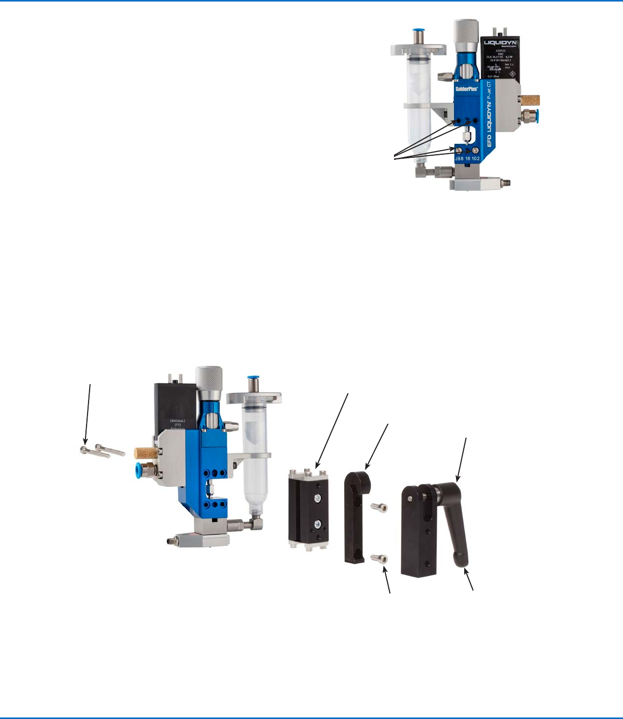
Quick-Mounting
An optional quick-mounting bracket is available for faster valve
removal and installation. Once the valve is installed using the quick-
mounting components, it can be easily removed or installed using
the quick-release fastener. Refer to “Quick-Release Valve Mounting
Components” on page38 for the quick-mounting kit part number.
You will need the following items:
• Vibration decoupler
• Quick-release fastener
• 2 M4 hex screws (minimum length: 10 mm)
• Hex wrench, size 2.5
• Hex wrench, size 3.0
Example of the quick-release mounting option
M3 x 30
mounting
screws
Vibration decoupler
Quick-release fastener
Hook (hooks into the
quick-release fastener)
M4 x 30 mounting
screws (for mounting
onto a socket; not
included)
Lever (secures the hook)
M3 mounting
hole locations