Nordson_EFD_P-Jet_SolderPlus_Operating_Manual.pdf - 第25页
Liquidyn P-Jet SolderPlus Jet Valve 25 www.nordsonefd.com info@nordsonefd.com +1-401-431-7000 Sales and service of Nordson EFD dispensing systems are available worldwide. Initial Startup This section provides recommendat…
Liquidyn P-Jet SolderPlus Jet Valve
24 www.nordsonefd.com info@nordsonefd.com +1-401-431-7000 Sales and service of Nordson EFD dispensing systems are available worldwide.
Installation Example
Item Description
Pneumatic connections
• Compressed air tube, 6 mm OD
• Dry, filtered air pressure, oil-free
• Filter grade: 40 µm
• Regulated by a precision pressure regulator
• Operating pressure limit: 3–8 bar (44–116 psi)
Fluid connection
• Syringe barrel accessories with compressed 4 mm air tubing
• Fluid pressure limit: 100 bar (1450 psi)
Electrical connections
• Supplied M8 valve cable from the valve to a Liquidyn valve controller or a higher-
level controller, such as a PLC
• Power supply: 24 VDC
• Power consumption: 0.5 Amp (peak 5.0 Amp)
Optional
• Nozzle heater (controlled by a temperature control unit)
• Process equipment (such as a laser light barrier for dot recognition or a cleaning
station for nozzles)
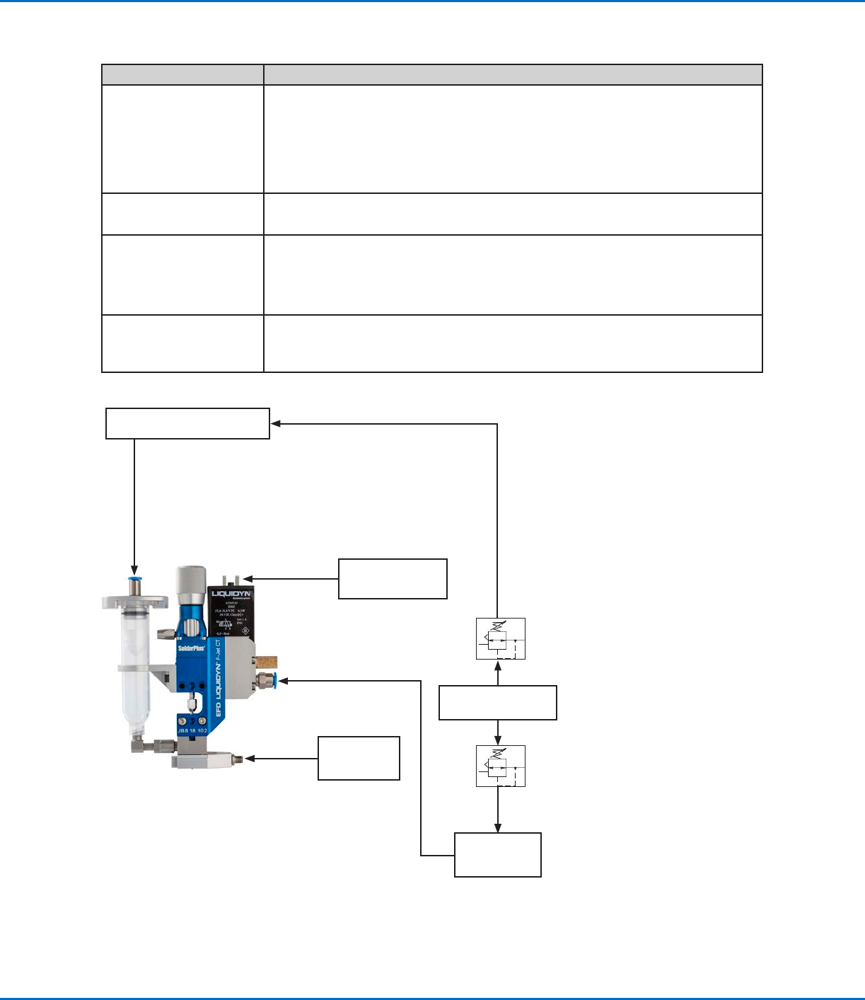
Liquidyn P-Jet SolderPlus valve connection diagram
Syringe barrel connection
Higher-level controller
(e.g., PLC)
Valve cable
4 mm air supply tubing
Fluid pressure
Precision
pressure
regulator
Precision
pressure
regulator
Air pressure source
Pressure
accumulator
(at least 0.4 liter)
Operating pressure
6 mm air supply tubing
P-Jet
SolderPlus
Temperature
controller (e.g.,
V200, T10)
Nozzle heater
cable
Liquidyn P-Jet SolderPlus Jet Valve
25www.nordsonefd.com info@nordsonefd.com +1-401-431-7000 Sales and service of Nordson EFD dispensing systems are available worldwide.
Initial Startup
This section provides recommendations for system startup and operation. System startup for the valve depends on
the control unit. If you are using a Nordson EFD Liquidyn valve controller, obtain the controller manual. If you are
using higher-level controller, the control is set up by the customer.
CAUTION
Before switching on the system, ensure that all electrical and pneumatic connections are connected correctly and
fully functioning.
1. Check electrical and pneumatic connections.
2. Switch on the control unit.
3. Turn on the air supplies.
4. (Solder paste applications only) If using the P-Jet SolderPlus valve in a solder paste dispensing
application, refer to “Appendix C, Special Instructions for Solder Paste Dispensing” on page47 for
steps that apply only to solder paste dispensing.
5. (All applications except solder paste applications) Use the following actions to set up and test the valve
operation using the control system manual or the customer-supplied control system and documentation. Refer
to “Parameter Settings” on page26 for information and recommendations on system setup.
a. Trigger the valve until the material to be dispensed leaves the nozzle opening. Place a collecting container or
paper sheet underneath the valve.
b. Clean the nozzle tip with a lint-free cloth.
c. Set the distance between the nozzle and the target (such as a sample product).
d. Initiate several dispense cycles to test the valve operation.
e. Evaluate the dispensing results and make adjustments until the desired dispensing performance is achieved.
Refer to “Parameter Settings” on page26 and to “Recommended Setup Adjustments” on page27 for
detailed information on system setup and adjustment.
6. To ensure optimal valve performance, maintain the system as described under “Service” on page30.
Liquidyn P-Jet SolderPlus Jet Valve
26 www.nordsonefd.com info@nordsonefd.com +1-401-431-7000 Sales and service of Nordson EFD dispensing systems are available worldwide.
Parameter Settings
The following table provides recommended settings for initial startup and testing of the valve operation. Detailed
information on each parameter is shown after the table.
Parameter Description Recommendation
Pulse Time The electrical trigger pulse of the valve, starting at 2 ms. 6 ms starting value
Frequency The number of tappet movements per second. 10Hz starting value
Fluid pressure The flow rate of the material supply; should be set to produce a
consistent volume.
1.0 bar (14.5 psi)
starting value
Operating pressure The setting of the tappet force screw; can be adjusted to fine-tune
the dispensing result.
6 bar (87 psi) starting
value
Stroke adjustment The setting of the stroke adjustment knob, which changes the
vertical movement of the tappet.
Do not adjust
Nozzle heater
temperature
If applicable, the temperature setting for the nozzle heater. 36 °C (98.8 °F) when
open
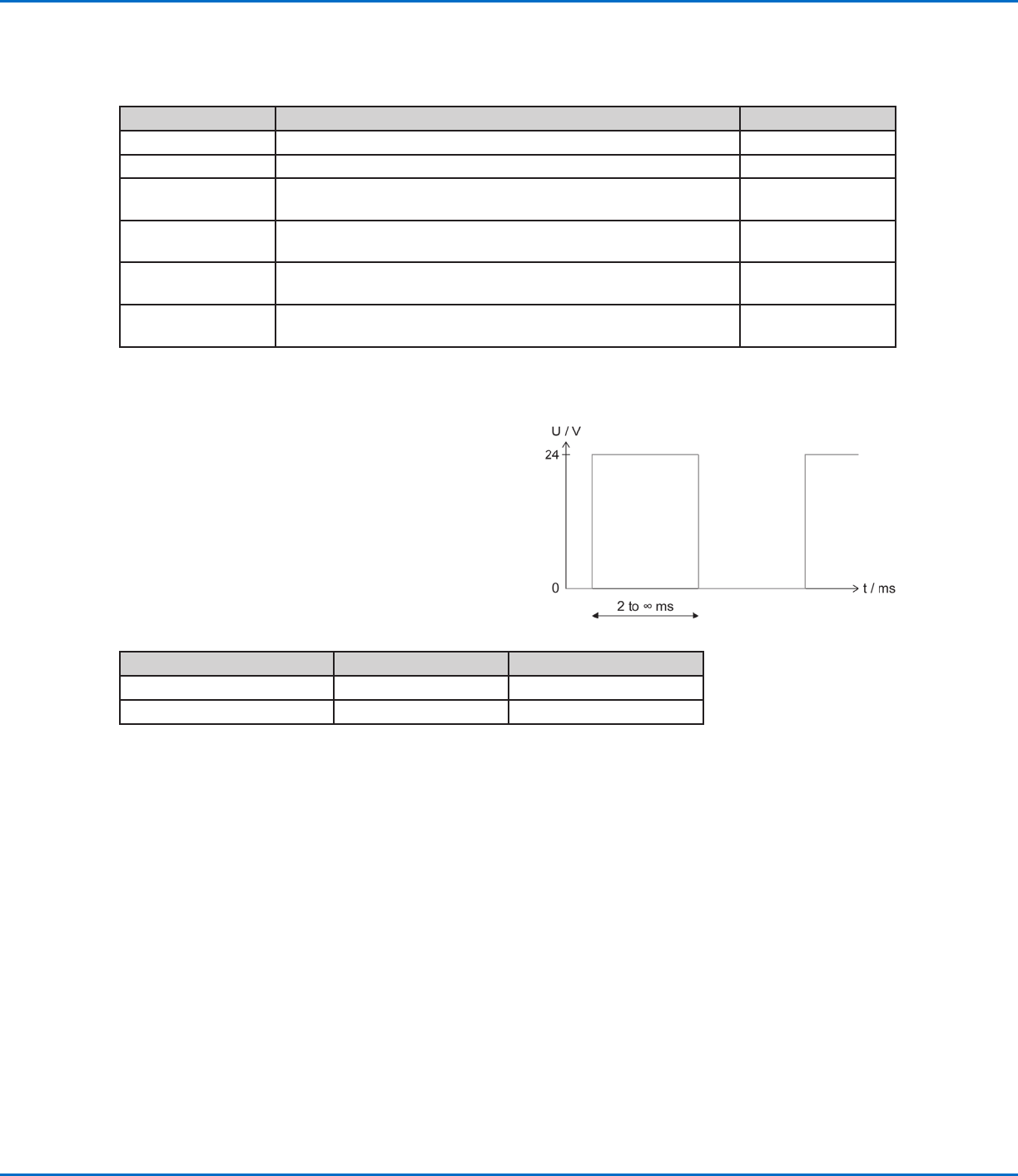
Pulse Time
The Pulse Time corresponds to the electrical trigger pulse, or opening time, of the valve, which is the primary control
of deposit size. The following conditions apply to Pulse Time:
• The pneumatically actuated dispensing nozzle remains
open as long as it is triggered.
• The dispensing volume is affected by the adjustment of
the triggering pulse.
• The minimum Pulse Time is 2 ms. The valve cannot
operate correctly at Pulse Times below 2ms.
Frequency
Frequency is the number of tappet movements per second.
A dispensing cycle consists of the Pulse Time and the pause time.
Physical Quantity Formula Unit
Frequency (f) f = 1 / T 1Hz (hertz) = 1 / s
Dispensing cycle T = 1 / f 1 s (second) = 1 / Hz
1 ms = 0.001 s (second)
Higher-level controllers may not allow you to enter the exact frequency. If such cases, frequency is set using the
length of the pulse and the pause time.