Printer 600 Adjustable Screen Mount.pdf - 第10页
$'-867$ %/(6&5(( 102817 $60 0(&+$1 ,&$/'(7$ ,/ 12.10 Technical Reference Manual Chapter Issue 3 May 03 We b Assemblies Fitted to either end of the lef t and right hand rail assemblies, t he we…
$'-867$%/(6&5((102817$60
0(&+$1,&$/'(7$,/
Chapter Issue 3 May 03 Technical Reference Manual 12.9
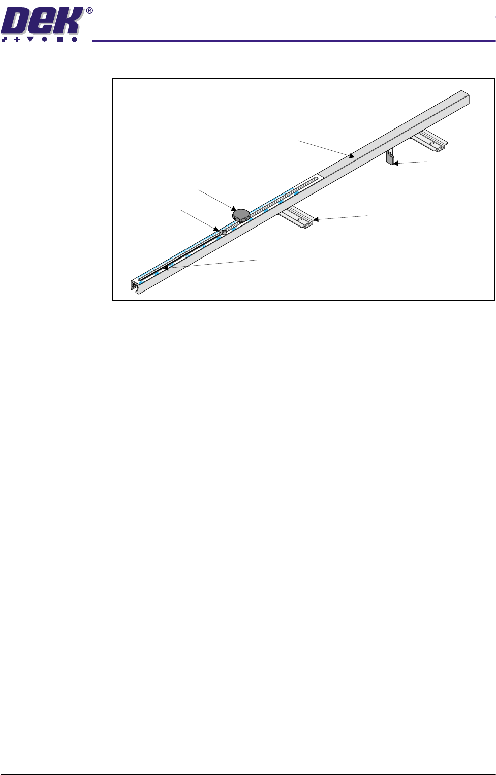
Depth Adjuster
Figure 12-6 Depth Adjuster
The depth adjuster consists of the following:
• Lockable sliding pointer
• Stencil stop
• Guide tube
The depth adjuster is fitted to the right hand chase rail assembly via two
brackets. The adjuster can be repositioned on the chase rail to accommodate
small screens by provision of two sets of key shaped mounting holes on the
brackets.
The sliding pointer is attached to a sliding guide strip which is slid into the top
of guide tube. The pointer is locked in position by means of clamping the guide
strip to the top of the guide tube by a threaded locking star grip. A metric and
an imperial scale is affixed to the guide tube for precise adjustment of the chase
to accommodate all sizes of screen. The stencil end stop attached to the end of
the sliding guide strip correctly positions the screen in the chase for printing.
Stencil Stop
Scale
Bracket
(in two positions)
Star Grip
Pointer
Guide Tube
$'-867$%/(6&5((102817$60
0(&+$1,&$/'(7$,/
12.10 Technical Reference Manual Chapter Issue 3 May 03
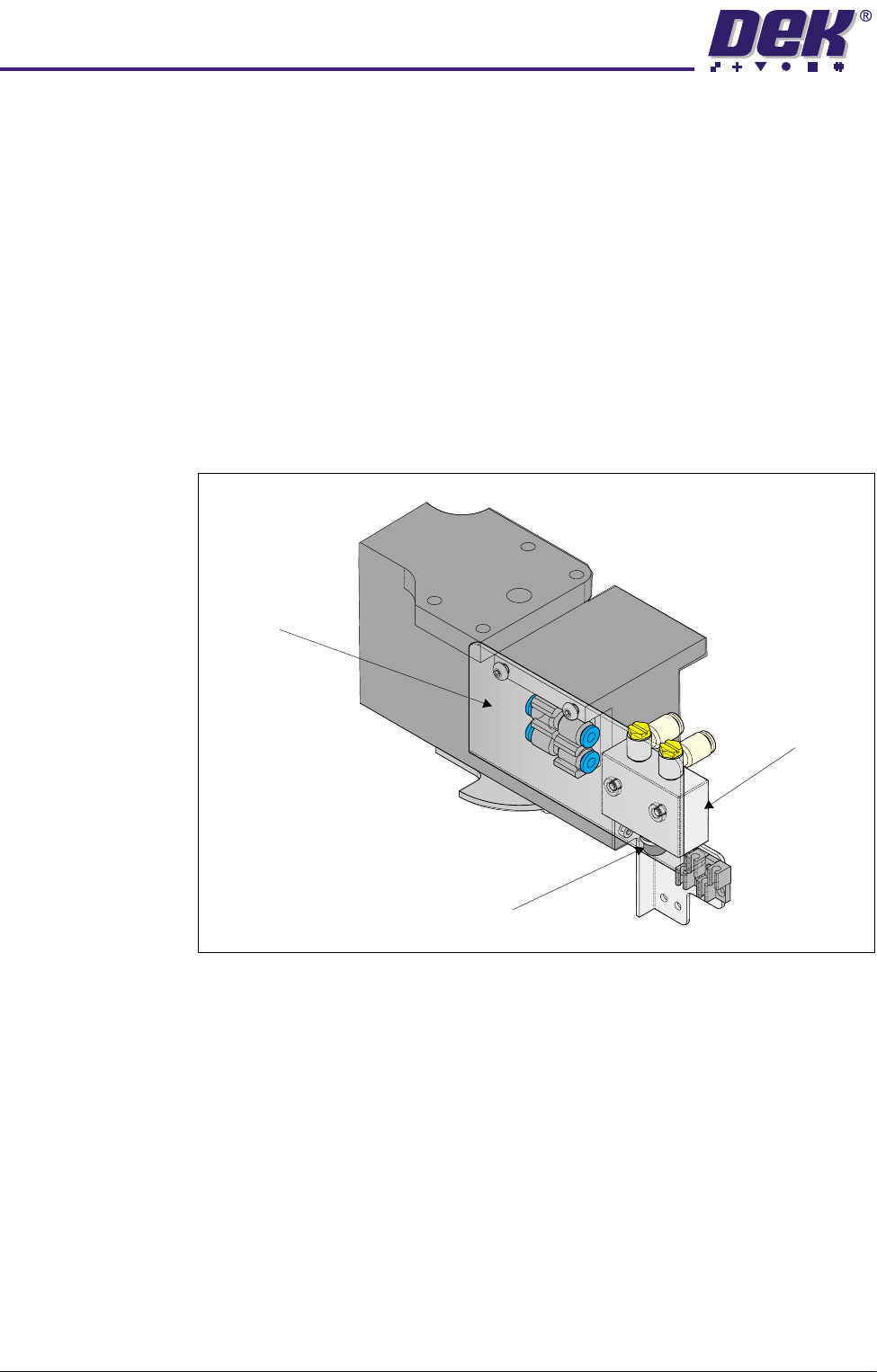
Web Assemblies Fitted to either end of the left and right hand rail assemblies, the web assemblies
allow for adjustment of the rails to accommodate for different size screens. The
webs clamp onto the linear ball bush shafts by means of a spring loaded locking
piston. Pneumatic pressure is applied to the locking piston compressing the
locking spring and releasing the web assembly from the linear ball bush shaft.
Hence, the rail assembly width can now be adjusted.
Pneumatic pressure is applied to the web assemblies via the valve fitted to the
front web assemblies’ rail width brackets. The user operates the appropriate
valve applying pneumatic pressure to the front and rear web assemblies
simultaneously, resulting in the web assembly being released from the linear
ball bush shaft allowing the rail to be adjusted as required.
On completion of the adjustment, the user releases the valve releasing the
pneumatic pressure applied to the webs allowing the locking shaft piston to
clamp onto the linear ball bush shaft under spring action.
Figure 12-7 Front Web Assembly
Rail Width
Bracket
Push Button
Pneumatic Valve
$'-867$%/(6&5((102817$60
'5,9(6$1'6(16256
Chapter Issue 3 May 03 Technical Reference Manual 12.11
DRIVES AND SENSORS
Motors There are no motors associated with this module.
Sensors
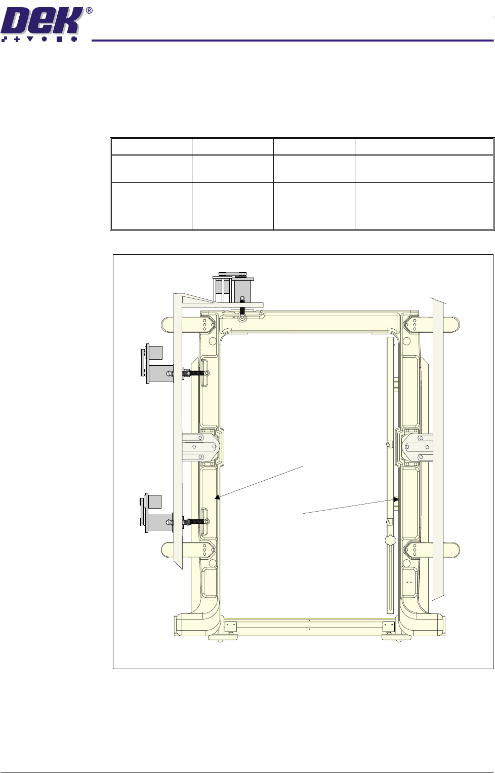
Figure 12-8 Location of Screen at Centre Sensor
Name Type Test Point Functional Description
Screen at Centre
(Tx)
Through Beam
Opto (13SE07)
MultiMove X12 Sends a beam of light to be
detected by the receiver.
Screen at Centre
(Rx)
Through Beam
Opto - (Long
Throw (13SE07)
MultiMove X12
DIG IN1
Senses a screen (stencil) has
been loaded into the chase as
the light beam has been broken
by the screen (stencil).
Screen at Centre
Sensor Receiver
Screen at Centre
Sensor Transmitter
Machine Front
Plan View of Chase