Printer 600 Adjustable Screen Mount.pdf - 第3页
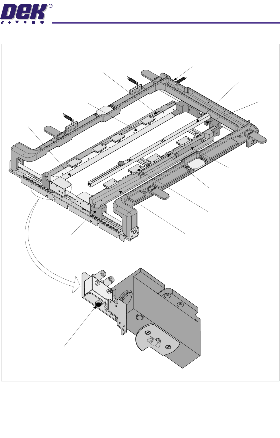
$'-867$ %/(6&5((1 02817 $60 02'8/( 29(59,(: Chapter Issue 3 May 03 Technical Reference Manual 12.3 Figure 12-1 Screen Change Overview Chase Casting Right Hand Rail Assembly Push Button V alve Left Han…

$'-867$%/(6&5((102817$60
02'8/(29(59,(:
12.2 Technical Reference Manual Chapter Issue 3 May 03
Elements The major elements of the screen change module are:
• The Chase C Casting
• Chase Right Hand Rail Assembly
• Chase Left Hand Rail Assembly
• Screen at Centre Sensor - Transmitter and Receiver
• Screen Depth Adjuster
• Web Assemblies (4 positions)
Operation The front cover is opened to gain access to the chase. The pneumatic push
buttons located on the underside of the front left and right hand web assemblies
are operated, releasing all four web assemblies on the front and rear linear ball
bush shafts. Releasing the web assemblies allows the user to adjust the
position of the chase left and right hand rail assemblies, to accommodate for
the appropriate size screen. The depth adjuster is set for either front or centre
justified screen image. The screen is loaded from the front of the machine and
slid into the machine along the top of stencil support plates. Three stencil
location leaf springs located in the right hand chase rail assembly ensure that
the screen is held in the correct location for printing, against the stencil guide
strips on the left hand chase rail assembly. The screen is pushed toward the
rear of the machine until it reaches the screen stop on the screen depth adjuster.
The user selects Screen Change, the four flap assemblies on each chase rail
assembly operate, clamping the screen to the stencil support plates.
$'-867$%/(6&5((102817$60
02'8/(29(59,(:
Chapter Issue 3 May 03 Technical Reference Manual 12.3
Figure 12-1 Screen Change Overview
Chase Casting
Right Hand Rail Assembly
Push Button Valve
Left Hand Rail Assembly
Screen Depth Adjuster
Screen Stop
Web Assembly
(in 4 positions)
Stencil Support Plate
(in 2 positions)
Stencil Guide Strip
(in 10 positions)
Stencil Location Leaf Spring
(in 3 positions)
Flap Assembly
(in 8 positions)
Chase Assembly (Isometric View)
View on Underside of Front Web Assembly
Double Acting
Pneumatic Cylinder
(in 2 positions)
$'-867$%/(6&5((102817$60
(/(&75,&$/6&+(0$7,&
12.4 Technical Reference Manual Chapter Issue 3 May 03
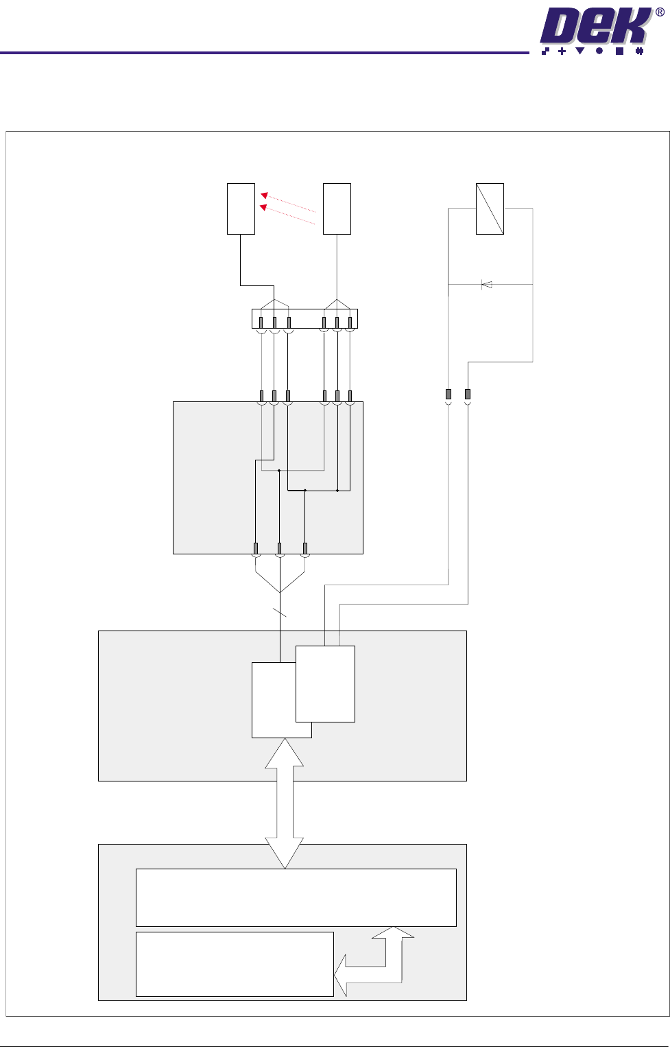
ELECTRICAL SCHEMATIC
PCB D
Cct Diag155529
Screen Clamp Solenoid
16SOL07
Screen at Centre
Through Beam Opto
13SE07
DSK8
0V
12V
DPL2
25
IN1
Source 0
0V
Rx
13PL01
Control Enclosure
Cct Diag 155502S2
Processor
ISA Bus
NextMove
ISA 3
ISA 10
Machine PC
Cct Diag 160991
MultiMove
X12
MultiMove
X13
CanBus
Tx
16SK07
+
-