Printer 600 Adjustable Screen Mount.pdf - 第5页
$'-867$ %/(6&5((1 02817 $60 0(&+$ 1,&$/'( 7$,/ Chapter Issue 3 May 03 Technical Reference Manual 12.5 MECHANICAL DET AIL Chase Casting The chase casti ng is a ‘ C ’ shaped one piece casting co…
$'-867$%/(6&5((102817$60
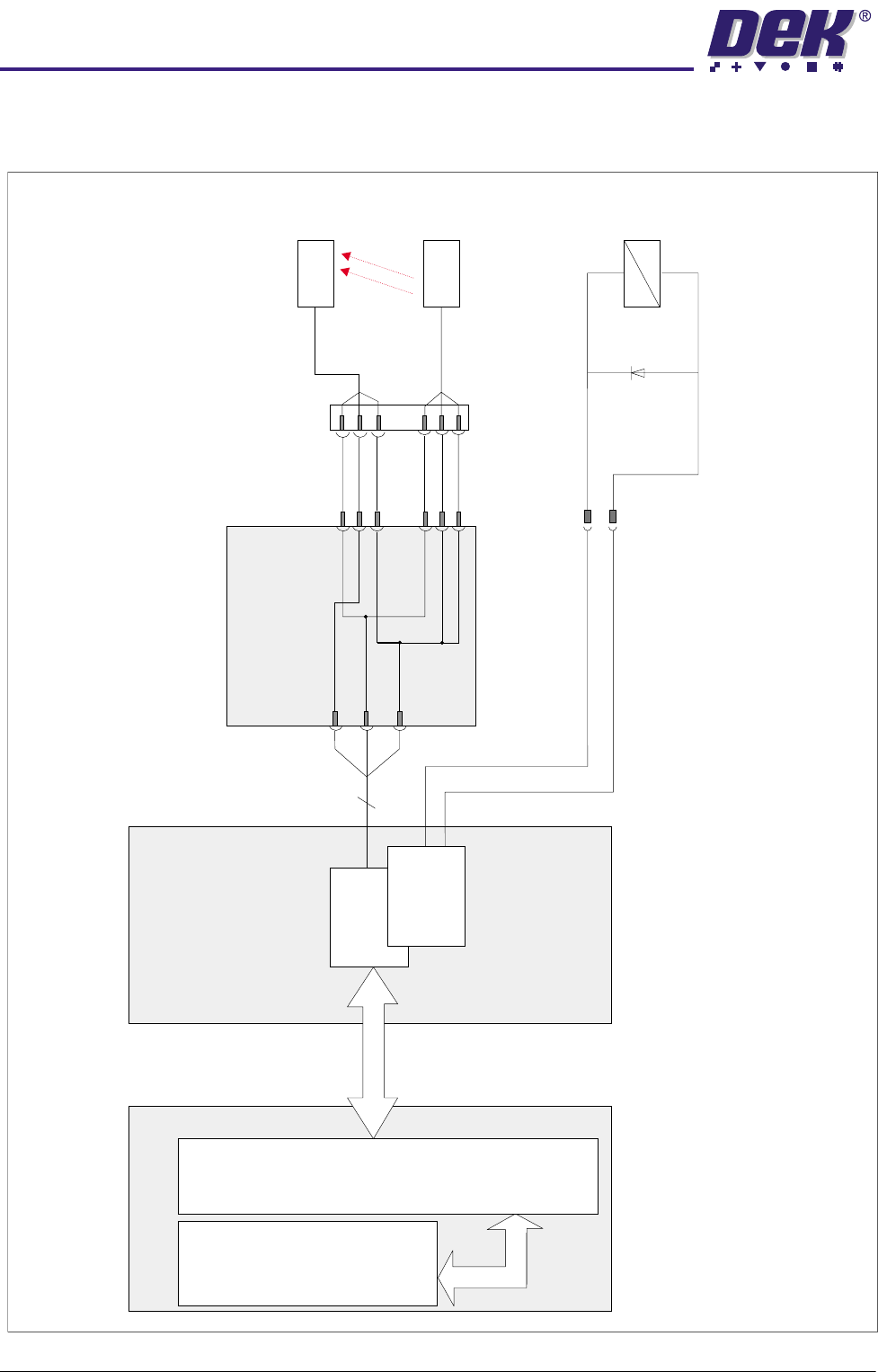
(/(&75,&$/6&+(0$7,&
12.4 Technical Reference Manual Chapter Issue 3 May 03
ELECTRICAL SCHEMATIC
PCB D
Cct Diag155529
Screen Clamp Solenoid
16SOL07
Screen at Centre
Through Beam Opto
13SE07
DSK8
0V
12V
DPL2
25
IN1
Source 0
0V
Rx
13PL01
Control Enclosure
Cct Diag 155502S2
Processor
ISA Bus
NextMove
ISA 3
ISA 10
Machine PC
Cct Diag 160991
MultiMove
X12
MultiMove
X13
CanBus
Tx
16SK07
+
-
$'-867$%/(6&5((102817$60
0(&+$1,&$/'(7$,/
Chapter Issue 3 May 03 Technical Reference Manual 12.5
MECHANICAL DETAIL
Chase Casting The chase casting is a ‘C’ shaped one piece casting containing the components
of the screen change module. It is the interface between the screen change
module and the machine. The chase is mounted on the machine chassis via
four chase bearing sets.
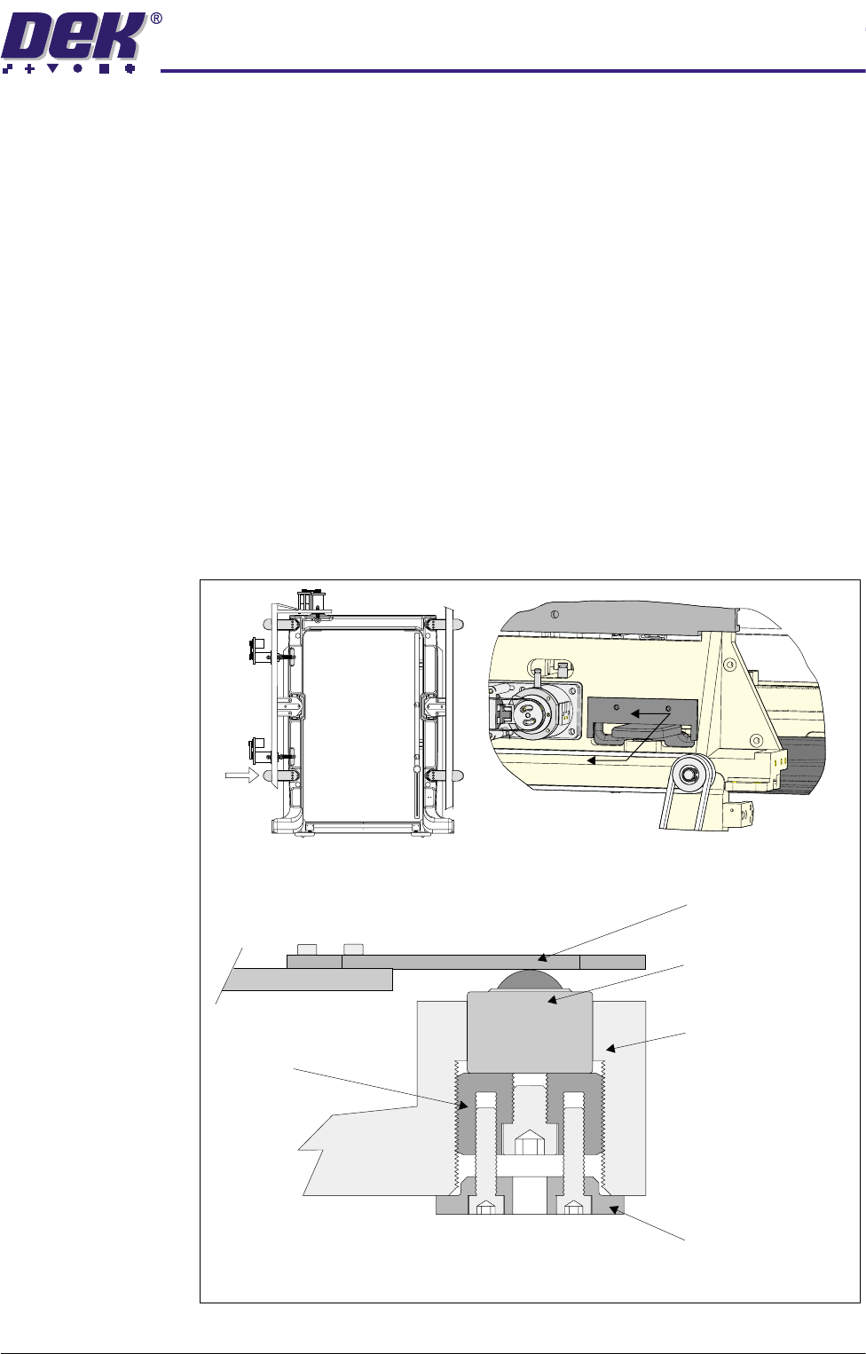
Chase Bearing The chase bearing consists of two major components:
• Roller Counter Plate
• Roller Bearing Assembly
The roller counter plates are attached to the chase in four positions. The roller
counter plates and roller bearing assemblies provide a floating chase arrange-
ment, the roller bearing assemblies are attached to the machine chassis and to
the chase via the roller counter plates.
The level of the chase relative to the rising table can be adjusted by varying the
height of the adjuster, using an Allen key through the access hole in the locking
collar, details of how this is achieved is given in the Adjustments and Settings
Section later in this chapter.
Figure 12-2 Chase Bearing
Sectional View ‘B - B’
(Through Chassis)
Locking Collar
Adjuster
Roller Counter Plate
Roller Bearing Assembly
Machine Chassis
Plan View of Chase
A
View on Arrow A
B
B
$'-867$%/(6&5((102817$60
0(&+$1,&$/'(7$,/
12.6 Technical Reference Manual Chapter Issue 3 May 03
Right Hand Rail
Assembly
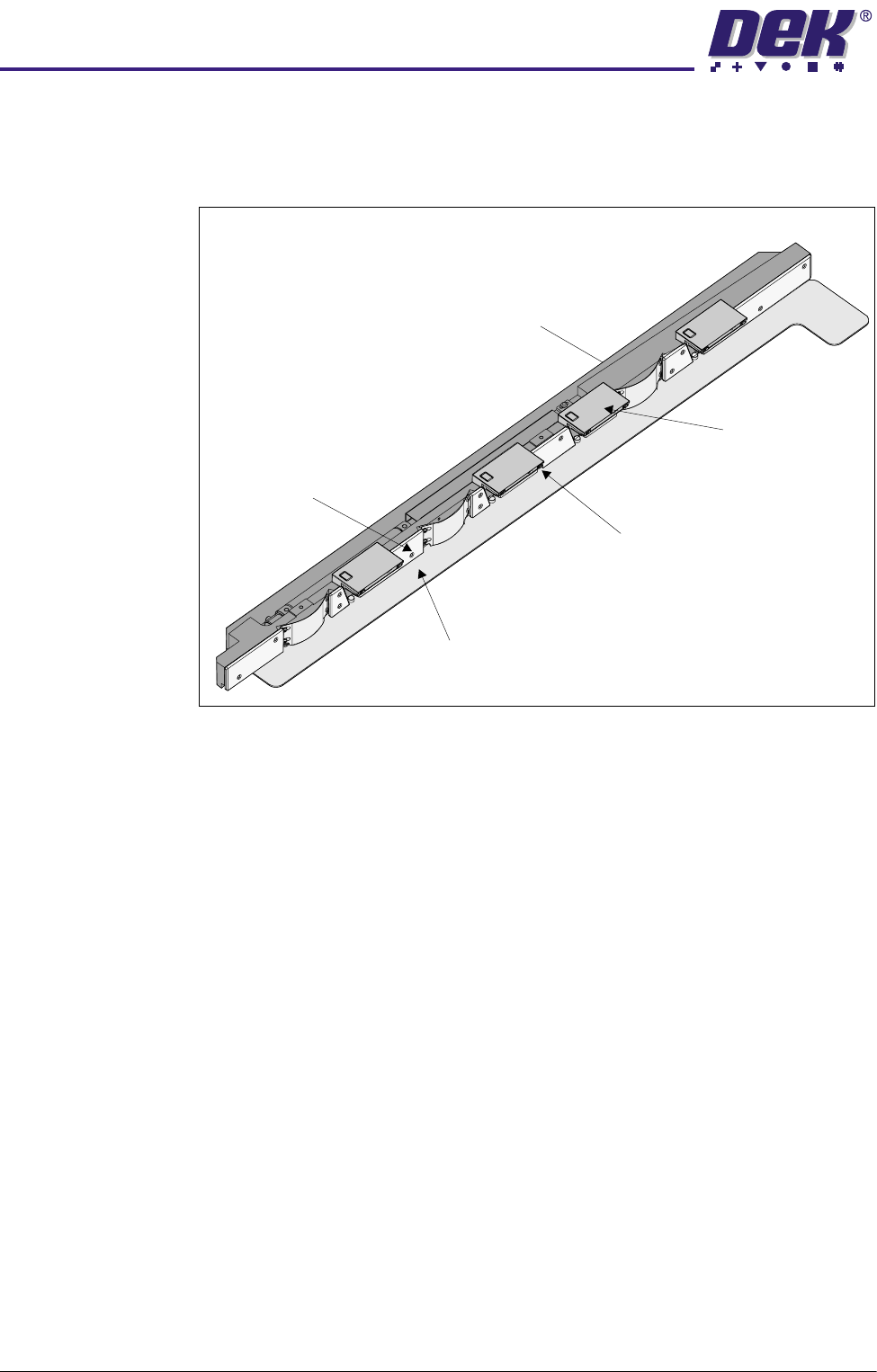
The right hand rail assembly is attached to the chase via a web assembly at
either end of the rail. The web assemblies clamp the rail to the front and rear
linear ball bush shafts securing the rail in the required position within the chase.
Figure 12-3 Right Hand Chase Rail Assembly
Attached to the inner face of the rail assembly are three location leaf springs
interspersed with segments of the nylon stencil guide strip. The springs provide
positive location for the stencil against the left hand rail assembly. Providing
support to a loaded stencil is the stainless steel stencil support plate attached
to the underside of the rail assembly.
A double acting pneumatic cylinder fitted to the external face of the rail assem-
bly is operated by the user via the Change Screen function button. Pneumatic
pressure is applied to the cylinder causing the cylinder piston to retract.
Attached to the end of the cylinder piston is a pulley. A fixed length cable
assembly is threaded from it’s retaining bracket around the piston pulley to a
pulley situated at the front end of the rail assembly. The cable runs from the front
of the rail to the cable retainer bracket at the rear of the rail assembly. The cable
assembly is routed around three pulleys associated with each of the four flap
assemblies. The two lower pulleys are fixed and the top pulley is attached to the
free end of the flap.
Stencil Guide Strips
(in 5 positions)
Stencil Location Leaf Springs
(in 3 positions)
Flap Assembly
(in 4 positions)
Stencil Support Plate
Screen at Centre
Opto Transmitter