Printer 600 Adjustable Screen Mount.pdf - 第7页
$'-867$ %/(6&5((1 02817 $60 0(&+$ 1,&$/'( 7$,/ Chapter Issue 3 May 03 Technical Reference Manual 12.7 Figure 12-4 Rail Assembly - Cable Routing As the pneu matic c ylinder piston is retract ed…
$'-867$%/(6&5((102817$60
0(&+$1,&$/'(7$,/
12.6 Technical Reference Manual Chapter Issue 3 May 03
Right Hand Rail
Assembly
The right hand rail assembly is attached to the chase via a web assembly at
either end of the rail. The web assemblies clamp the rail to the front and rear
linear ball bush shafts securing the rail in the required position within the chase.
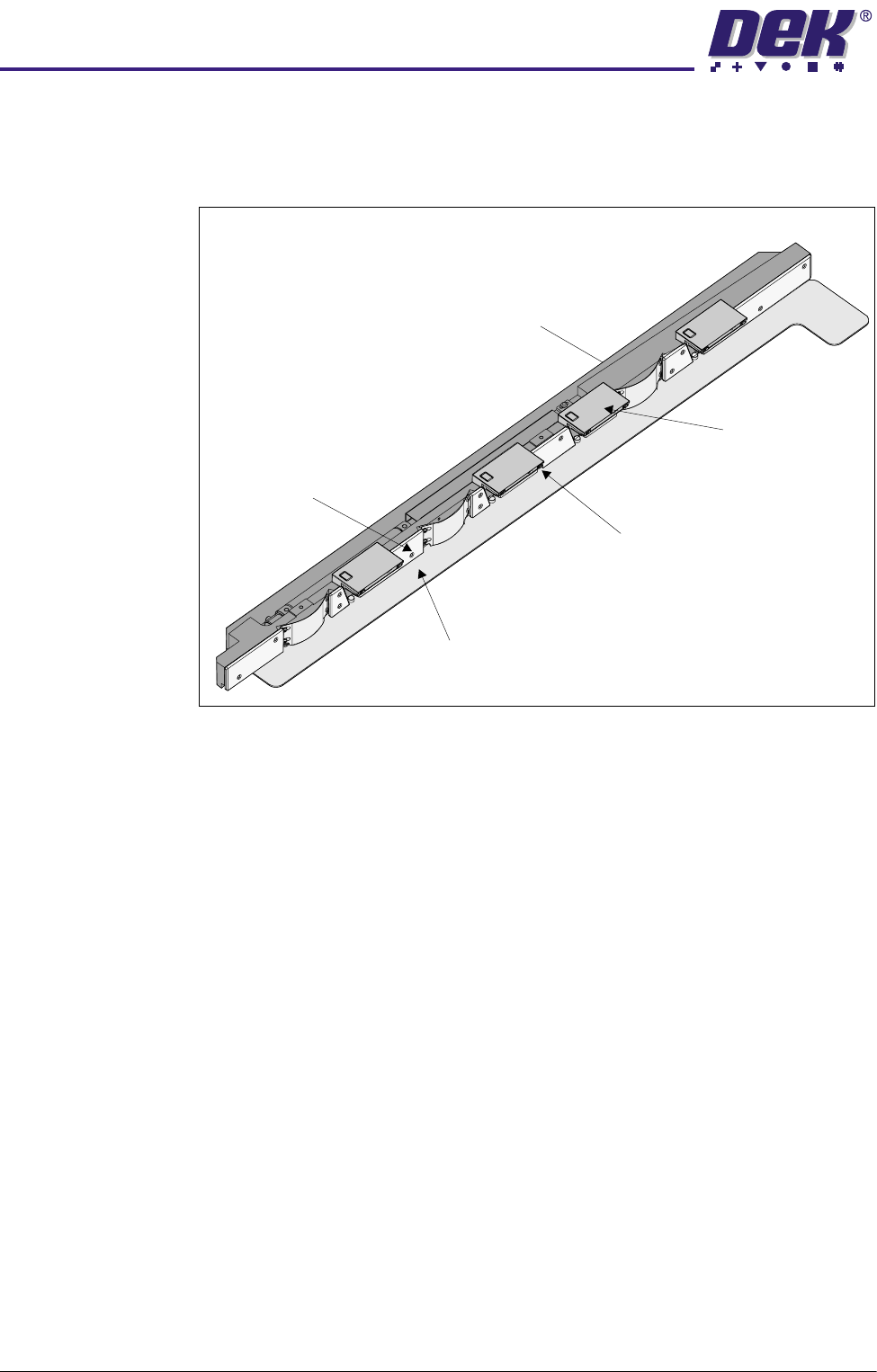
Figure 12-3 Right Hand Chase Rail Assembly
Attached to the inner face of the rail assembly are three location leaf springs
interspersed with segments of the nylon stencil guide strip. The springs provide
positive location for the stencil against the left hand rail assembly. Providing
support to a loaded stencil is the stainless steel stencil support plate attached
to the underside of the rail assembly.
A double acting pneumatic cylinder fitted to the external face of the rail assem-
bly is operated by the user via the Change Screen function button. Pneumatic
pressure is applied to the cylinder causing the cylinder piston to retract.
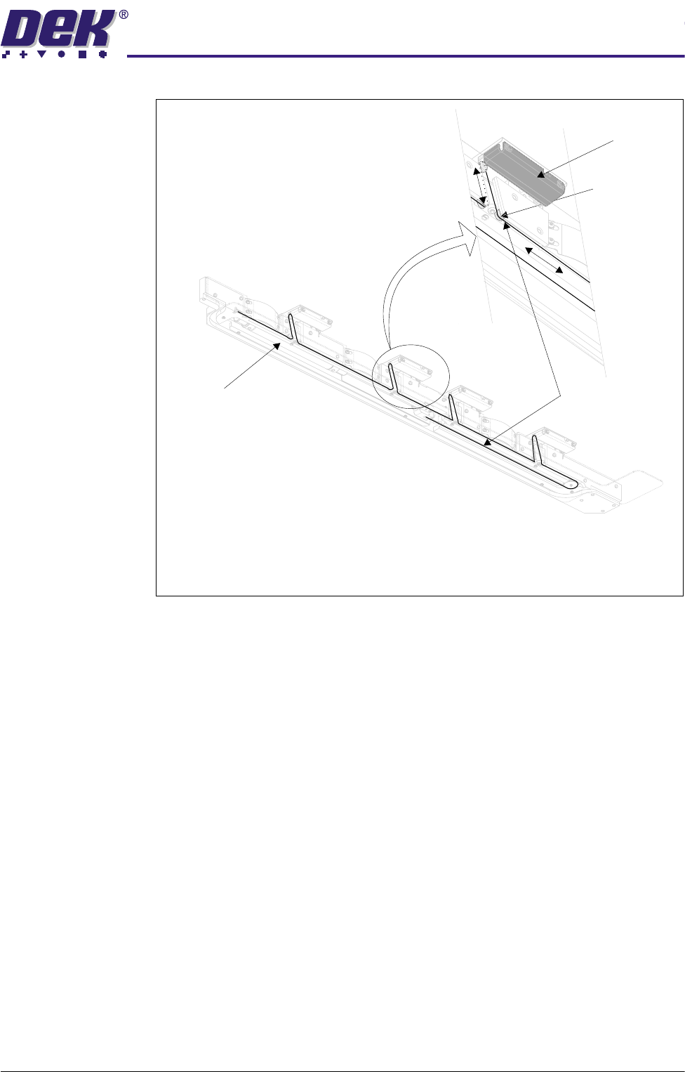
Attached to the end of the cylinder piston is a pulley. A fixed length cable
assembly is threaded from it’s retaining bracket around the piston pulley to a
pulley situated at the front end of the rail assembly. The cable runs from the front
of the rail to the cable retainer bracket at the rear of the rail assembly. The cable
assembly is routed around three pulleys associated with each of the four flap
assemblies. The two lower pulleys are fixed and the top pulley is attached to the
free end of the flap.
Stencil Guide Strips
(in 5 positions)
Stencil Location Leaf Springs
(in 3 positions)
Flap Assembly
(in 4 positions)
Stencil Support Plate
Screen at Centre
Opto Transmitter
$'-867$%/(6&5((102817$60
0(&+$1,&$/'(7$,/
Chapter Issue 3 May 03 Technical Reference Manual 12.7
Figure 12-4 Rail Assembly - Cable Routing
As the pneumatic cylinder piston is retracted the cable assembly is effectively
shortened causing the top pulley and hence the flap to be pulled down towards
the stencil support plate against spring pressure. The screen is now clamped
between the flaps and the stencil support plate.
To release the screen, pneumatic pressure is applied to the cylinder extending
the piston and lengthening the cable assembly. This allows the flaps to return
to the horizontal plane under spring pressure, releasing the screen. The routing
of the cable assembly within the rail assembly is shown in the diagram above.
The Screen at Centre opto transmitter is fitted to the right hand chase rail
assembly.
Flap Assembly
Pulley
(in 3 positions)
Pneumatic Cylinder
Cable Assembly
View on Underside of Rail Assembly
(Stencil Support and Guides Removed for Clarity)
$'-867$%/(6&5((102817$60
0(&+$1,&$/'(7$,/
12.8 Technical Reference Manual Chapter Issue 3 May 03
Left Rail Assembly The left hand chase rail assembly is attached to the chase assembly in a similar
manner to the right hand chase rail assembly. Web assemblies fitted to either
end of the rail, clamp the rail to the front and rear linear ball bush shafts within
the chase assembly.
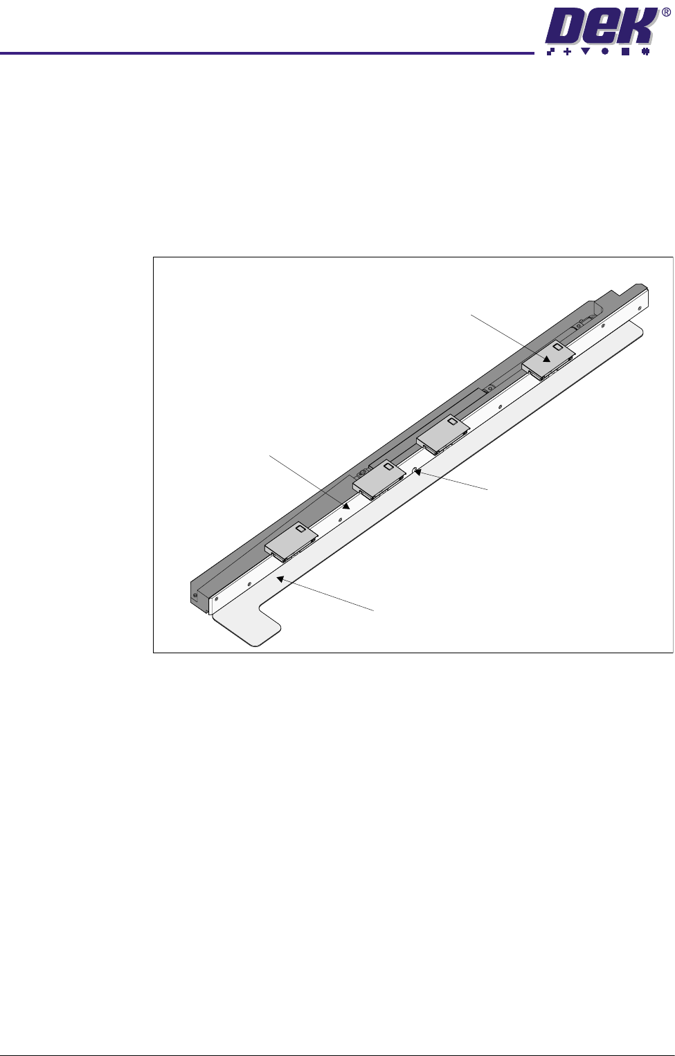
Attached to the inner face of the rail assembly are sections of the stencil guide
strip, providing a datum face for a loaded screen. The stencil support plate
attached to the underside of the rail assembly provides support to a loaded
screen.
Figure 12-5 Left Hand Chase Rail Assembly
A pneumatic double acting cylinder corresponding to the one fitted in the right
hand chase assembly works in a similar manner to the right hand cylinder
raising or lowering the four flap assemblies, clamping or releasing the screen.
The Screen at Centre opto receiver is fitted to the left hand chase rail assembly.
Stencil Guide Strips
(in 5 positions)
Screen at Centre
Opto Receiver
Stencil Support Plate
Flap Assembly
(in 4 positions)