Printer 600 Adjustable Screen Mount.pdf - 第27页
$'-867$ %/(6&5((1 02817 $60 &$/,%5$7,21 6 Chapter Issue 3 May 03 Technical Reference Manual 12.27 4. T i ghten the tw o locking nuts. Associated Calibrations and Adjustment s The setti ngs shown below s…
$'-867$%/(6&5((102817$60
&$/,%5$7,216
12.26 Technical Reference Manual Chapter Issue 3 May 03
CALIBRATIONS
Chase to Table
Level
NOTE
This procedure requires the use of a special DEK Test Plate, therefore contact
DEK Customer Support before commencing.
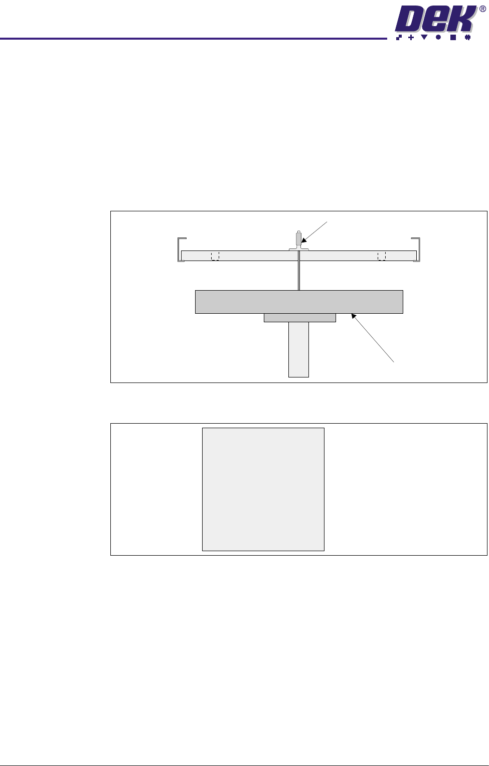
The chase to table level is checked by measuring down to 5 points on the rising
table surface from a special DEK Test Plate which simulates a screen fitted in
the chase.
A datum reading is taken from the centre hole E, the range of readings must not
exceed 0.15mm of the datum.
Figure 12-10 Chase to Table Level Setting
Figure 12-11 Test Plate Recordings
Chase to Table
Level Adjustment
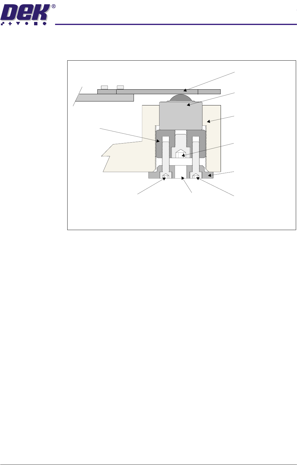
If adjustment is required, the bearing roller(s) at the appropriate corner may be
adjusted to obtain the correct depth range.
NOTE
Be careful that this does not result in one corner of the chase ‘floating’, ie load
not being spread evenly over the four support rollers.
1. Slacken the two locking screws using a 2.5mm Allen key.
2. Using a 4mm Allen key through the access hole in the locking collar, turn the
adjuster screw, which also turns the adjuster and the locking collar. This
action raises and lowers the roller bearing assembly by the amount indi-
cated by the chase to table level check.
3. Verify that the correct setting has been achieved.
Depth Micrometer
Rising Table
A
B
CD
E
A .....................mm
B .....................mm
C .....................mm
D .....................mm
E .....................mm
$'-867$%/(6&5((102817$60
&$/,%5$7,216
Chapter Issue 3 May 03 Technical Reference Manual 12.27
4. Tighten the two locking nuts.
Associated
Calibrations and
Adjustments
The settings shown below should be checked subsequent to the following
calibrations and adjustments.
1. Chase to Table level:
• Vision Height (Camera System Module)
• Vision System Calibration (Camera System Module):
Stage 1 - Calibrate Vision
Stage 2 - Calibrate Offset
• Chase Clamp Air Gap (Screen Alignment Module)
Access Hole
Locking Screw
Locking Screw
Adjuster Screw
Cutaway Side View of Chase Support
Locking Collar
Adjuster
Roller Counter Plate
Roller Bearing Assembly
Machine Chassis

$'-867$%/(6&5((102817$60
&$/,%5$7,216
12.28 Technical Reference Manual Chapter Issue 3 May 03