Printer 600 Adjustable Screen Mount.pdf - 第16页
$'-867$ %/(6&5(( 102817 $60 5(3/$&(0( 17352&('8 5(6 12.16 Technical Reference Manual Chapter Issue 3 May 03 5. Disconnect the following pneumatic pipes shown in t he graphic below: 6. Disconne…
$'-867$%/(6&5((102817$60
5(3/$&(0(17352&('85(6
Chapter Issue 3 May 03 Technical Reference Manual 12.15
REPLACEMENT PROCEDURES
Chase Rail Assembly
WARNING
BOARD CLAMPS. EXTREME CARE MUST BE EXERCISED WHEN WORKING IN
THE TOOLING AREA OF THE MACHINE TO AVOID INJURY. THE FOILS ON THE
FRONT AND REAR BOARD CLAMPS ARE VERY SHARP.
WARNING
COMPRESSED AIR. COMPRESSED AIR SHOULD NEVER IMPINGE UPON THE
BODY. PORTS, PIPES, ETC MUST NEVER BE BLOCKED BY HAND. BEFORE
CONNECTING ANY PNEUMATIC EQUIPMENT TO A COMPRESSED AIR SUPPLY,
ALL MOUNTINGS, FITTINGS, PIPEWORK AND ELECTRICAL CONNECTIONS
SHOULD BE REMOVED FOR SAFETY. NO PIPEWORK ALTERATIONS OR
REMOVAL OF FITTINGS SHOULD BE ATTEMPTED WITH AIR SUPPLIES
CONNECTED.
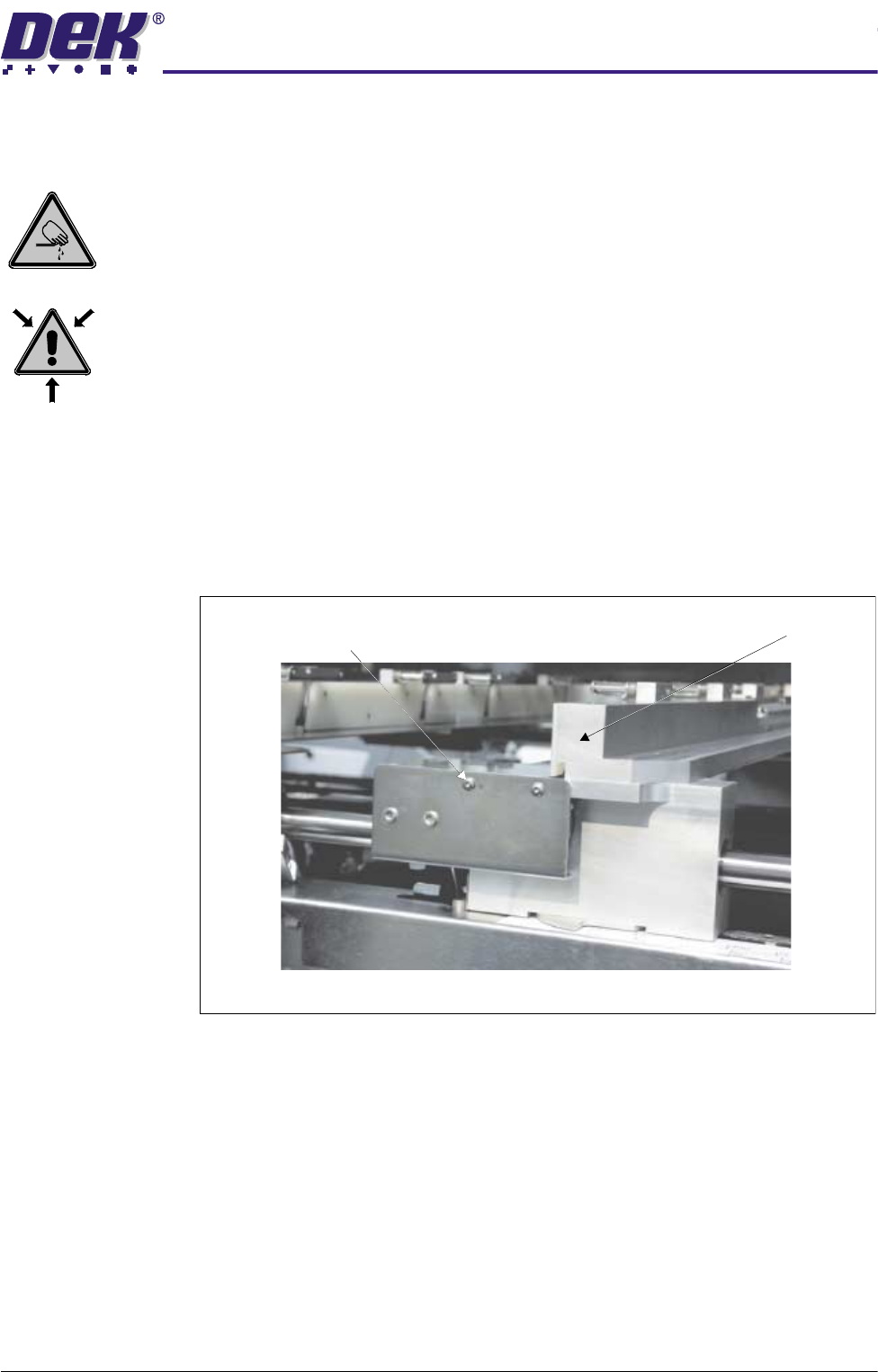
Removal 1. Open the front printhead cover and centralise the chase rail assemblies.
2. Power down the machine and disconnect the pneumatic supply to the
machine.
3. Remove the two web bracket securing screws.
4. Tilt the web bracket forward to expose the pneumatic pipes.
Chase Rail AssemblyWeb Assembly Bracket Securing Screws
(in 2 Positions)
View on Front of Machine
$'-867$%/(6&5((102817$60
5(3/$&(0(17352&('85(6
12.16 Technical Reference Manual Chapter Issue 3 May 03
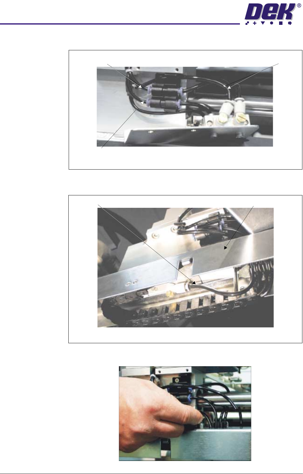
5. Disconnect the following pneumatic pipes shown in the graphic below:
6. Disconnect from the underside of the rail width scale assembly the pneu-
matic pipe marked Rail Lock - Front.
7. Uncouple from the tube clip the pneumatic supply pipe to the Rail Lock -
Front (disconnected in Step 6).
Screen Clamps - Off
Screen Clamps - On
Rail Lock
View on Front of Machine
Rail Lock - Front Rail Width Scale Assembly
View on Underside of Rail Width Scale Assembly
$'-867$%/(6&5((102817$60
5(3/$&(0(17352&('85(6
Chapter Issue 3 May 03 Technical Reference Manual 12.17
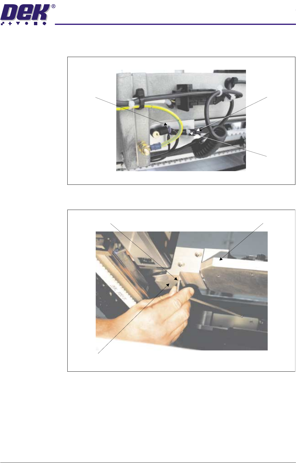
8. Gain access to the rear of the chase assembly. Disconnect the pneumatic
and electrical connectors to the rear web and remove the cable tie.
9. At the rear web assembly, remove the three chase rail assembly securing
bolts.
10.At the rear face of the front web assembly, remove the two chase rail
Pneumatic
Connection
Electrical
Connection
Cable Tie
View on Rear of ASM
Chase Rail Securing Bolt - Tighten Chase Rail Assembly
Rear Web Assembly
View on Chase Rail Assembly