Printer 600 Adjustable Screen Mount.pdf - 第17页
$'-867$ %/(6&5((1 02817 $60 5(3/$&(0(1 7352&('85 (6 Chapter Issue 3 May 03 Technical Reference Manual 12.17 8. Gain access to the r ear of the ch ase assembly . Disconnec t the pneumatic and e…
$'-867$%/(6&5((102817$60
5(3/$&(0(17352&('85(6
12.16 Technical Reference Manual Chapter Issue 3 May 03
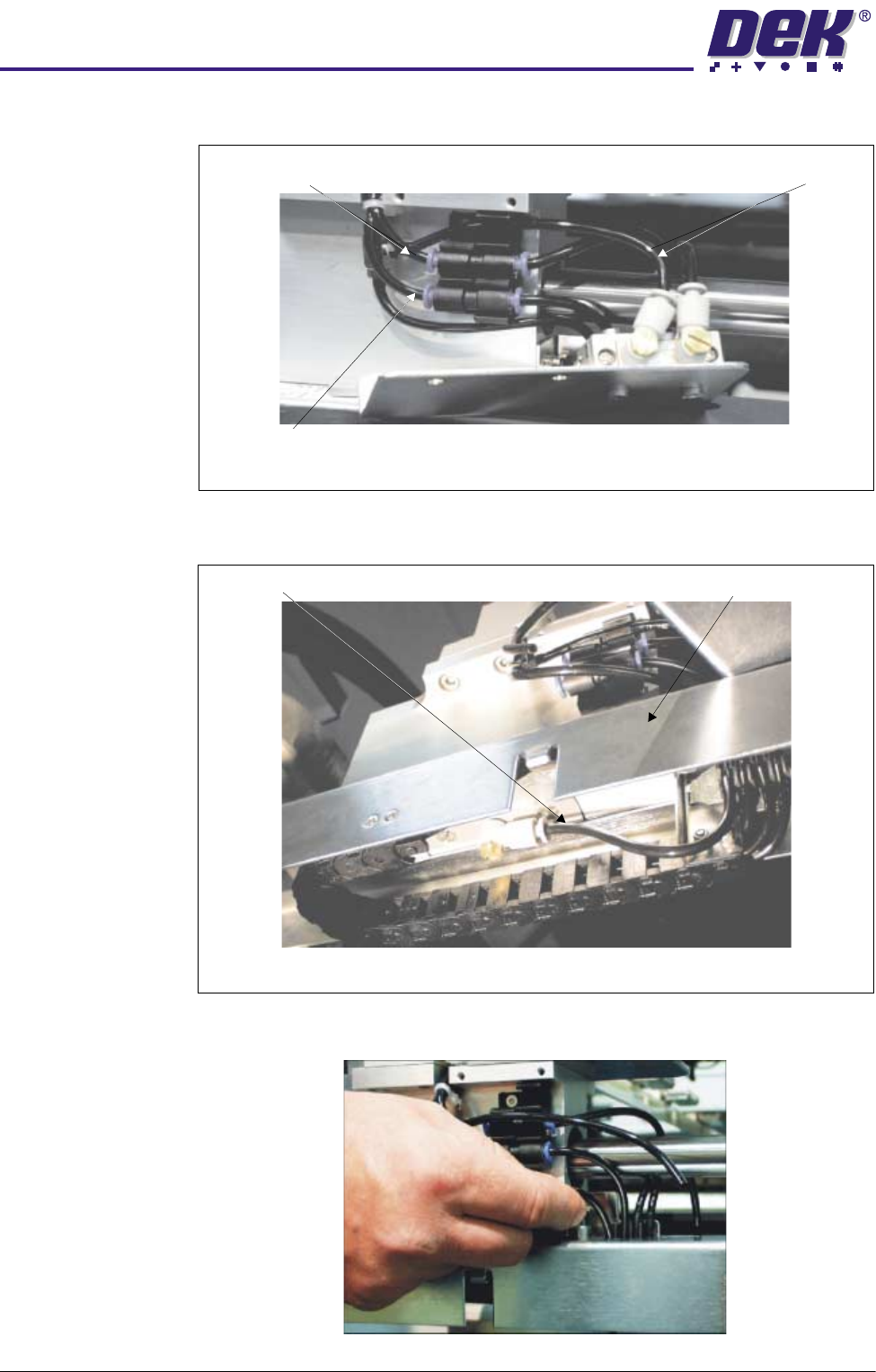
5. Disconnect the following pneumatic pipes shown in the graphic below:
6. Disconnect from the underside of the rail width scale assembly the pneu-
matic pipe marked Rail Lock - Front.
7. Uncouple from the tube clip the pneumatic supply pipe to the Rail Lock -
Front (disconnected in Step 6).
Screen Clamps - Off
Screen Clamps - On
Rail Lock
View on Front of Machine
Rail Lock - Front Rail Width Scale Assembly
View on Underside of Rail Width Scale Assembly
$'-867$%/(6&5((102817$60
5(3/$&(0(17352&('85(6
Chapter Issue 3 May 03 Technical Reference Manual 12.17
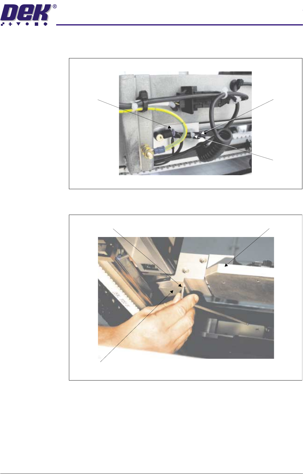
8. Gain access to the rear of the chase assembly. Disconnect the pneumatic
and electrical connectors to the rear web and remove the cable tie.
9. At the rear web assembly, remove the three chase rail assembly securing
bolts.
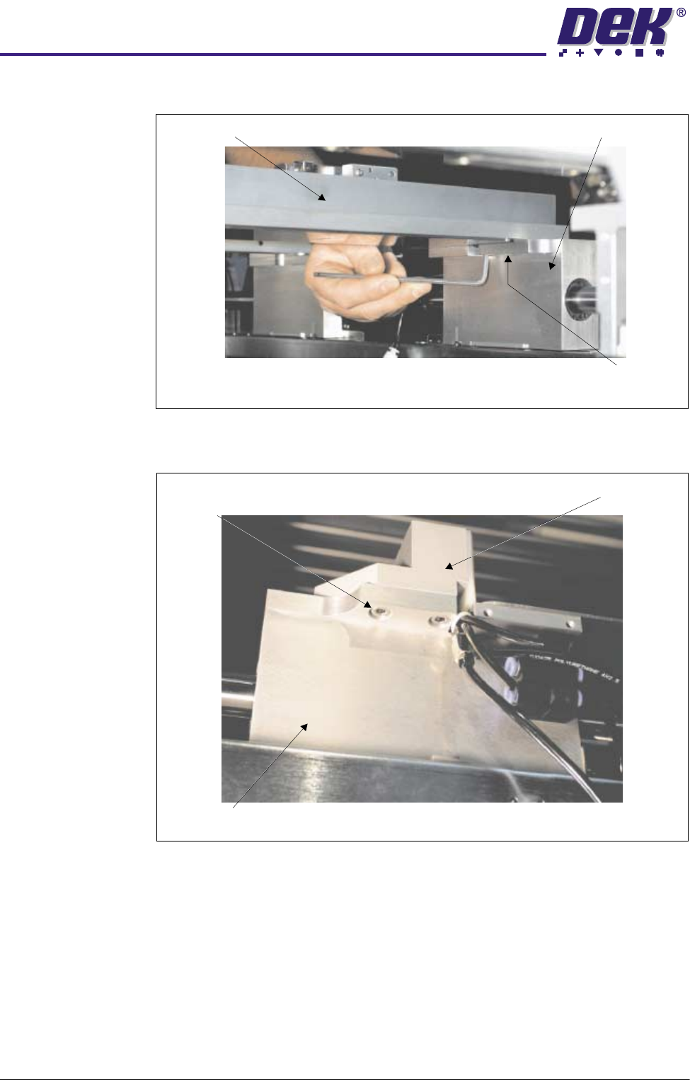
10.At the rear face of the front web assembly, remove the two chase rail
Pneumatic
Connection
Electrical
Connection
Cable Tie
View on Rear of ASM
Chase Rail Securing Bolt - Tighten Chase Rail Assembly
Rear Web Assembly
View on Chase Rail Assembly
$'-867$%/(6&5((102817$60
5(3/$&(0(17352&('85(6
12.18 Technical Reference Manual Chapter Issue 3 May 03
assembly securing bolts.
11. At the front face of the front web assembly, remove the two chase rail
assembly securing bolts.
12.Lift the rear end of the chase rail assembly clear of the rear web assembly.
Carefully feed the electrical connector and pneumatic pipe through the
Chase Rail Assembly
Securing Bolts
(in 2 Positions)
Front Web Assembly
Rear View of the Front Web Assembly
Securing Bolts
(in 2 Positions)
Front Web Assembly
Chase Rail Assembly
Front View of Front Web Assembly