Printer 600 Adjustable Screen Mount.pdf - 第18页
$'-867$ %/(6&5(( 102817 $60 5(3/$&(0( 17352&('8 5(6 12.18 Technical Reference Manual Chapter Issue 3 May 03 assembly s ecuring bolt s. 1 1. At the fr ont face of the front web assembly , remov…
$'-867$%/(6&5((102817$60
5(3/$&(0(17352&('85(6
Chapter Issue 3 May 03 Technical Reference Manual 12.17
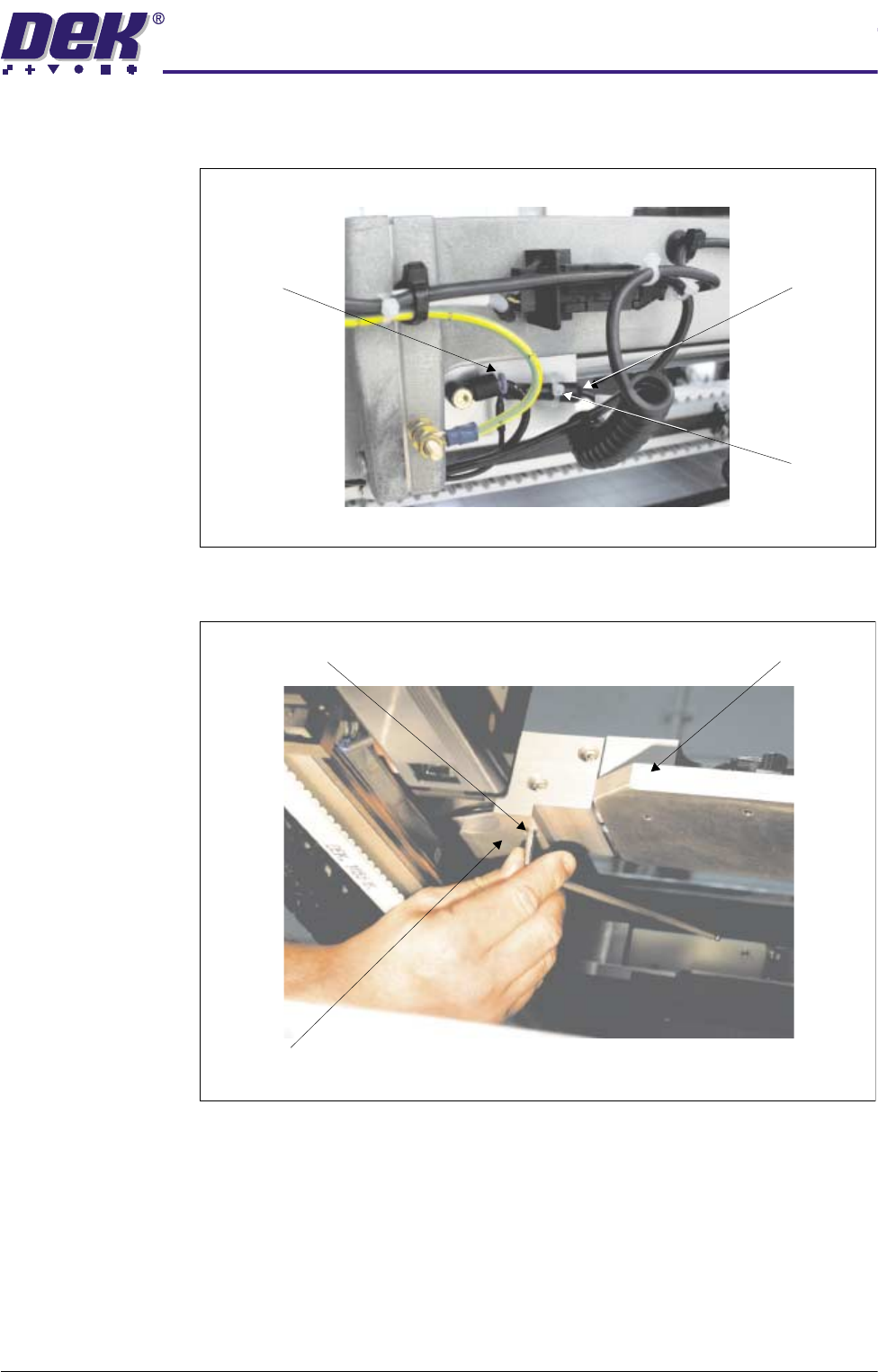
8. Gain access to the rear of the chase assembly. Disconnect the pneumatic
and electrical connectors to the rear web and remove the cable tie.
9. At the rear web assembly, remove the three chase rail assembly securing
bolts.
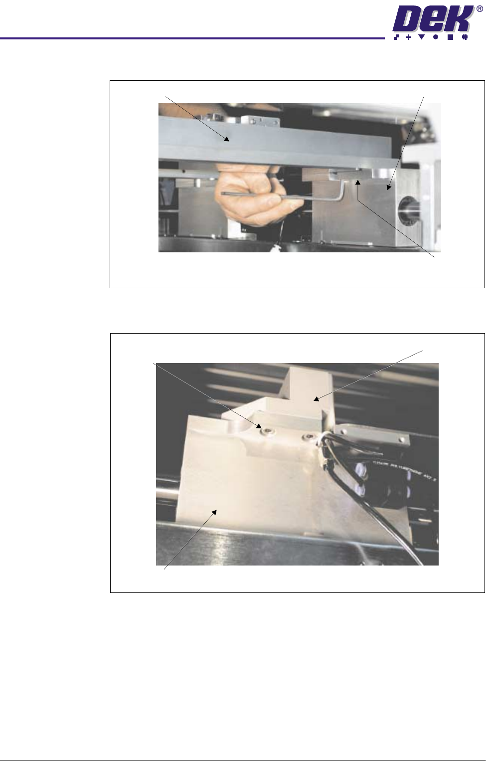
10.At the rear face of the front web assembly, remove the two chase rail
Pneumatic
Connection
Electrical
Connection
Cable Tie
View on Rear of ASM
Chase Rail Securing Bolt - Tighten Chase Rail Assembly
Rear Web Assembly
View on Chase Rail Assembly
$'-867$%/(6&5((102817$60
5(3/$&(0(17352&('85(6
12.18 Technical Reference Manual Chapter Issue 3 May 03
assembly securing bolts.
11. At the front face of the front web assembly, remove the two chase rail
assembly securing bolts.
12.Lift the rear end of the chase rail assembly clear of the rear web assembly.
Carefully feed the electrical connector and pneumatic pipe through the
Chase Rail Assembly
Securing Bolts
(in 2 Positions)
Front Web Assembly
Rear View of the Front Web Assembly
Securing Bolts
(in 2 Positions)
Front Web Assembly
Chase Rail Assembly
Front View of Front Web Assembly
$'-867$%/(6&5((102817$60
5(3/$&(0(17352&('85(6
Chapter Issue 3 May 03 Technical Reference Manual 12.19
access hole in the rear web.
13.Replace the chase rail assembly onto the rear web assembly ensuring the
electrical cable and pneumatic pipe are not trapped.
14.From the front of the machine carefully lift out the chase rail assembly
ensuring the electrical cable and pneumatic pipe does not snag on any part
of the machine.
Fitment 1. Carefully place the chase rail assembly onto the front and rear web assem-
blies from the front of the machine, ensuring the pneumatic pipes and
electrical cables are not trapped under the rail assemblies.
2. At the rear web assembly, lift the end of the chase rail assembly and first,
thread the electrical cable and subsequently the pneumatic pipe through the
access hole in the web.
3. Loosely assemble the chase rail securing bolts (in seven positions) to the
front and rear web assemblies.
4. At the rear web assembly, tighten the two horizontal chase rail securing bolts
until the outer face of the rail just touches the web face.
CAUTION
SECURING BOLTS.
The two rear web horizontal chase rail securing bolts
must not be fully tighten at this juncture otherwise, damage to the
machine may occur.
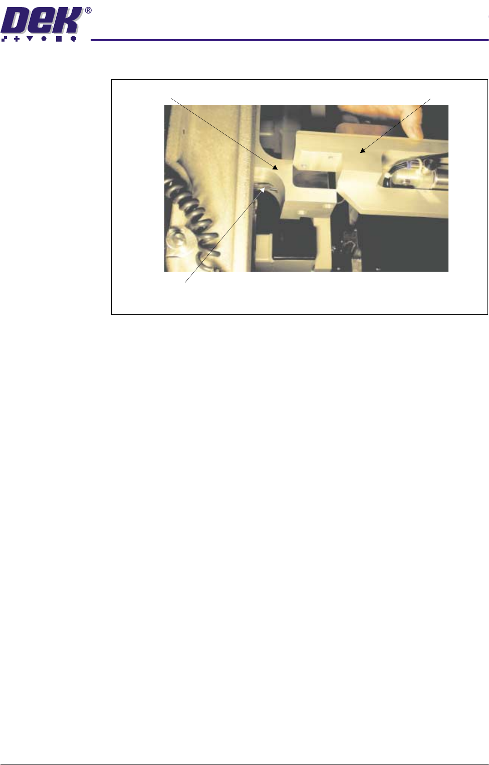
Rear Web Assembly Chase Rail Assembly
Electrical Connector
Plan View on Rear Web Assembly