Printer 600 Adjustable Screen Mount.pdf - 第8页
$'-867$ %/(6&5(( 102817 $60 0(&+$1 ,&$/'(7$ ,/ 12.8 Technical Reference Manual Chapter Issue 3 May 03 Lef t Rail Assembly The lef t hand cha se rail assembl y is att ached t o the chase a ssem…
$'-867$%/(6&5((102817$60
0(&+$1,&$/'(7$,/
Chapter Issue 3 May 03 Technical Reference Manual 12.7
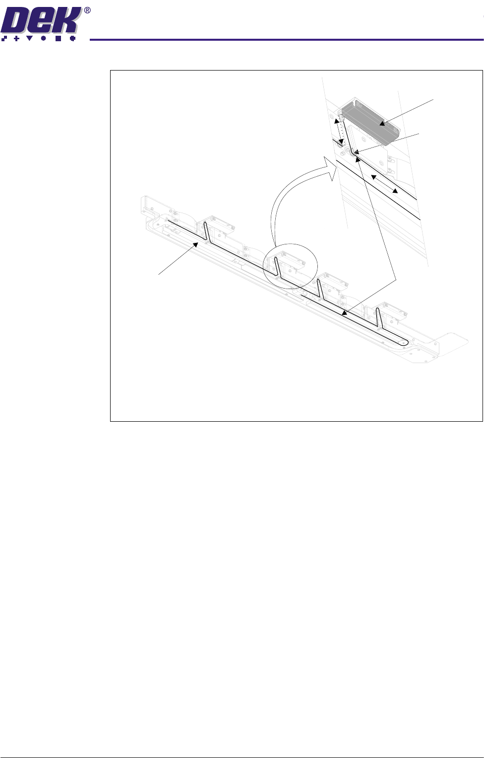
Figure 12-4 Rail Assembly - Cable Routing
As the pneumatic cylinder piston is retracted the cable assembly is effectively
shortened causing the top pulley and hence the flap to be pulled down towards
the stencil support plate against spring pressure. The screen is now clamped
between the flaps and the stencil support plate.
To release the screen, pneumatic pressure is applied to the cylinder extending
the piston and lengthening the cable assembly. This allows the flaps to return
to the horizontal plane under spring pressure, releasing the screen. The routing
of the cable assembly within the rail assembly is shown in the diagram above.
The Screen at Centre opto transmitter is fitted to the right hand chase rail
assembly.
Flap Assembly
Pulley
(in 3 positions)
Pneumatic Cylinder
Cable Assembly
View on Underside of Rail Assembly
(Stencil Support and Guides Removed for Clarity)
$'-867$%/(6&5((102817$60
0(&+$1,&$/'(7$,/
12.8 Technical Reference Manual Chapter Issue 3 May 03
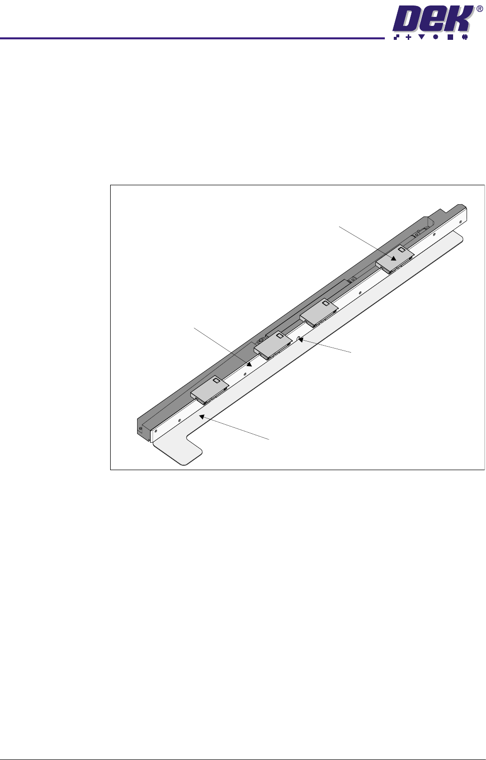
Left Rail Assembly The left hand chase rail assembly is attached to the chase assembly in a similar
manner to the right hand chase rail assembly. Web assemblies fitted to either
end of the rail, clamp the rail to the front and rear linear ball bush shafts within
the chase assembly.
Attached to the inner face of the rail assembly are sections of the stencil guide
strip, providing a datum face for a loaded screen. The stencil support plate
attached to the underside of the rail assembly provides support to a loaded
screen.
Figure 12-5 Left Hand Chase Rail Assembly
A pneumatic double acting cylinder corresponding to the one fitted in the right
hand chase assembly works in a similar manner to the right hand cylinder
raising or lowering the four flap assemblies, clamping or releasing the screen.
The Screen at Centre opto receiver is fitted to the left hand chase rail assembly.
Stencil Guide Strips
(in 5 positions)
Screen at Centre
Opto Receiver
Stencil Support Plate
Flap Assembly
(in 4 positions)
$'-867$%/(6&5((102817$60
0(&+$1,&$/'(7$,/
Chapter Issue 3 May 03 Technical Reference Manual 12.9
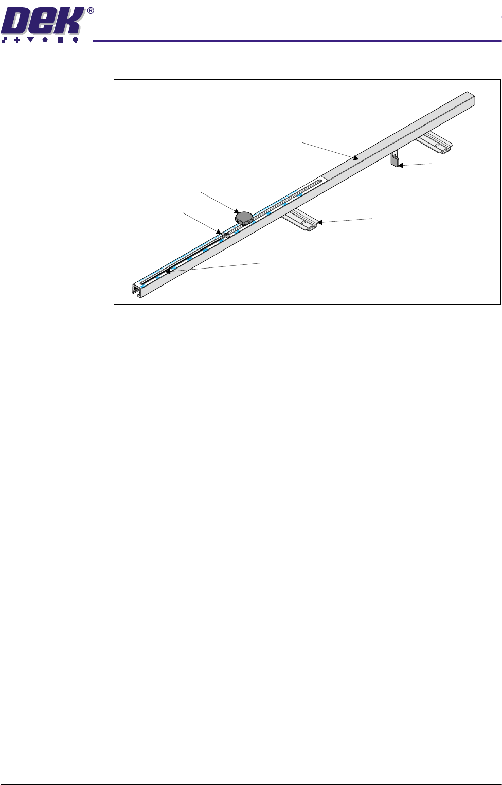
Depth Adjuster
Figure 12-6 Depth Adjuster
The depth adjuster consists of the following:
• Lockable sliding pointer
• Stencil stop
• Guide tube
The depth adjuster is fitted to the right hand chase rail assembly via two
brackets. The adjuster can be repositioned on the chase rail to accommodate
small screens by provision of two sets of key shaped mounting holes on the
brackets.
The sliding pointer is attached to a sliding guide strip which is slid into the top
of guide tube. The pointer is locked in position by means of clamping the guide
strip to the top of the guide tube by a threaded locking star grip. A metric and
an imperial scale is affixed to the guide tube for precise adjustment of the chase
to accommodate all sizes of screen. The stencil end stop attached to the end of
the sliding guide strip correctly positions the screen in the chase for printing.
Stencil Stop
Scale
Bracket
(in two positions)
Star Grip
Pointer
Guide Tube