Printer 600 Adjustable Screen Mount.pdf - 第24页
$'-867$ %/(6&5(( 102817 $60 5(3/$&(0( 17352&('8 5(6 12.24 Technical Reference Manual Chapter Issue 3 May 03 7. Feed the loom through th e channel of the chase rail assembly . 8. Refit the st e…
$'-867$%/(6&5((102817$60
5(3/$&(0(17352&('85(6
Chapter Issue 3 May 03 Technical Reference Manual 12.23
Screen at Centre
Sensor
To replace the screen at centre sensor transmitter or receiver the appropriate
chase rail assembly is to be removed from the machine (see Chase Rail -
Removal procedure earlier in this section).
1. Place the chase rail assembly on a level surface with the stencil support
plate uppermost. Unscrew the nine M3 countersunk stencil support plate
retaining screws and remove the plate.
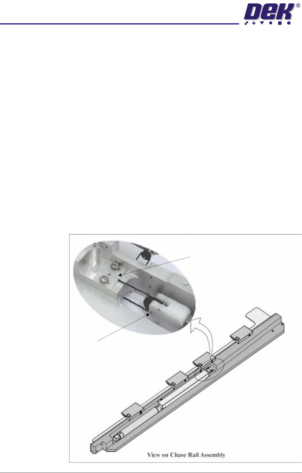
2. Remove the screen at centre M3 button headed retaining screw from the
centre of the sensor body.
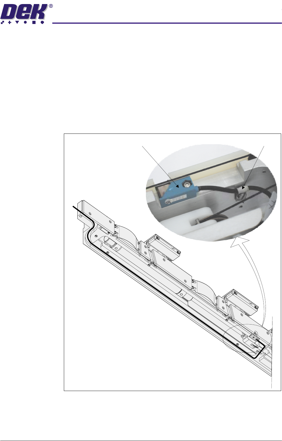
3. Release the sensor loom from the ‘P’ clip fitted adjacent to the pneumatic
cylinder pulley.
4. Remove and discard the sensor loom.
5. Fit the the replacement sensor to the chase rail assembly and secure with
the M3 button headed screw.
6. Fit the ‘P’ clip to the sensor loom and secure with the pan headed screw.
Ensure the loom runs beneath the cable assembly.
View on Underside of Chase Rail Assembly
(Stencil Support Plate Removed)
'P' Clip
Screen at Centre Sensor
$'-867$%/(6&5((102817$60
5(3/$&(0(17352&('85(6
12.24 Technical Reference Manual Chapter Issue 3 May 03
7. Feed the loom through the channel of the chase rail assembly.
8. Refit the stencil support plate and secure with the nine M3 countersunk
retaining screws.
9. To refit the chase rail assembly to the machine (see Chase Rail Fitment
procedure earlier in this section.
Cable Assembly To replace the cable assembly the appropriate chase rail assembly is to be
removed from the machine (see Chase Rail - Removal procedure earlier in this
section)
Removal 1. Place the chase rail assembly on a level surface with the stencil support
plate uppermost. Unscrew the nine M3 countersunk stencil support plate
retaining screws and remove the plate.
2. Turn the chase rail assembly through 90°. Unscrew the stencil guide strip
M3 pan head retaining screws and remove the stencil guides for access.
3. Rotate the chase rail assembly until the flap assemblies are uppermost.
Loosen the flap cover bracket retaining screws and remove the four flap
covers.
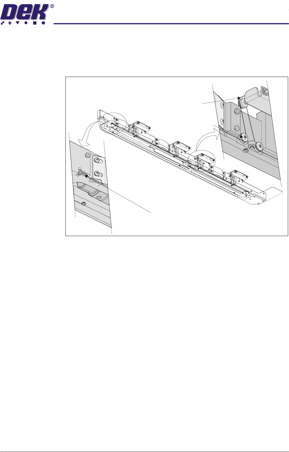
4. Lever the cable retainers from the topmost cable pulleys.
5. Unscrew the two cylinder cover securing screws and remove the cover to
gain access to the cable retainer bracket. Remove the two pan headed
retaining screws, the bracket and release the cable end.
Cable Retainer Bracket
Pulley Retaining Pin
$'-867$%/(6&5((102817$60
5(3/$&(0(17352&('85(6
Chapter Issue 3 May 03 Technical Reference Manual 12.25
6. Release the cylinder pulley retaining pin from the pulley block and remove
the pulley from the block releasing the cable assembly.
7. Rotate the chase rail assembly through 180°
8. Remove the cable end from the retaining slot in the chase rail assembly.
9. Un-thread the cable assembly from the cable pulleys and cylinder pulley.
Fitment 1. Fit the end of the new cable assembly to the retaining slot in the chase rail
assembly.
2. Thread the cable assembly around the four sets of three cable pulleys and
route the cable around the cylinder pulley.
3. Thread the cable assembly loosely around the pulley and refit the pulley to
the pulley block and secure with the retaining pin.
4. Clamp the cable end to the chase rail assembly with the cable retainer
bracket and secure with two M4 pan head screws. Refit the cylinder cover.
5. Clip the cable retainers over the topmost pulleys. Fit the flap cover brackets
over the flap assemblies and secure with M3 screws.
6. Using M3 pan head retaining screws refit the stencil guide strips to the chase
rail assembly.
7. Position the stencil support plate on the base of the chase rail assembly and
secure with nine M3 countersunk screws.
8. To refit the chase rail assembly to the machine (see Chase Rail Fitment
procedure earlier in this section.
Cable End
View on Underside of Chase Rail Assembly
Cable Retainer
Pulley
(in three positions)