00192299-02.pdf - 第103页
SIPLACE HS-50 2 Retrofitting Instructions: Mechanical Ceramic Subs trate Centering HS-50 01/01 Issue 2.7 Checking the Function 103 Å Duri ng the foll owing ste p, keep an eye on the subs trate and the clos ing move ment …

2 Retrofitting Instructions: Mechanical Ceramic Substrate Centering HS-50 SIPLACE HS-50
2.7 Checking the Function 01/01 Issue
102
&KHFNLQJWKH)XQFWLRQ
&KHF N LQJWKH)XQFWLRQRIWKH;&HQWHULQJ8QLW:,7+2876XEVWUDWH
Å Check WITHOUT substrate, whether the mechanical substrate centering unit opens and
closes correctly, i.e., whether the proximity switch (control LED) and solenoid valve operate
properly and the restrictor is set correctly.
Å In the "Transport functions" menu click on the button "
&HUDPLF VXEVWUDWH FHQWHULQJ
" in the
field "Processing area 1".
Ceramic substrate centering unit 1 will open.
Å Click on the button "
&HUDPLFVXEVWUDWHFHQWHULQJ
" again in the field "Processing area 1".
Ceramic substrate centering unit 1 will close.
Å Make certain that the lifting slide of the centering unit doesn’t bounce upon opening or it
opens too slowly:
- If it opens too slowly, the proximity switch signal does turn to 1 but it does so too late.
- If it bounces, the proximity switch becomes free again (signal 1 -> 0 -> 1).
Å If there is an error, correct the setting of the restrictor for the opening movement appropri-
ately (see Fig. 2.5.4 -> 7).
Å Proceed in a like manner for "Processing area 2".
Å <RXUQH [WVWHSLV WRFKHFN DQGDGMXVWWKHVWRSSHUSRVWLRQ
&KHFNLQJWKH2YHUDOO)XQFWLRQDQGWKH6WRSSHU3RVLWLRQ:,7+6XEVWUDWH
Conduct the following test run with substrate to check the function of the substrate centering unit
during the conveying process (lifting table up/down) and simultaneously to visually inspect that
the substrate is properly centered and thus that the stopper position is also correct.
NOTICE
These jobs must be carried out for each ceramic substrate centering unit, i.e., for each processing
area.
When the centering unit is open, the substrate edge pointing in the direction of the unloader must
still be 0.5 mm IN FRONT OF that of the unmovable roller of the fixed stop (see Fig. 2.7.2). When
the substrate is raised while the centering unit is moving upward, the stopper position must be ad-
justed in the direction of the X-centering station.
Å Select the menu "Transport functions".
Å Place the substrate on the input belt
SIPLACE HS-50 2 Retrofitting Instructions: Mechanical Ceramic Substrate Centering HS-50
01/01 Issue 2.7 Checking the Function
103
Å During the following step, keep an eye on the substrate and the closing movement of the X-
centering unit. The substrate is not to raise.
For the corresponding conveyor (processing area), select: PCB onto processing belt 1.
Å If the substrate is lifted when the open centering unit moves upward, you must adjust the
stopper position (see Section 2.7.3).
Å After the lifting table is raised, the x-centering unit close due to the tension spring on the flat
cylinder (no pressure applied, proximity switch signal = 0).
If an error message is displayed, see Section 2.7.4.
Å Select:PCB onto intermediate belt.
The X-centering unit must open before the lifting table moves down (pressure applied, proxim-
ity switch signal = 1
Å Carry out the above-described check on the function and the substrate/stopper position for pro-
cessing belt 2.
Å Select: PCB onto processing belt 2.
Å If necessary correct the stopper position (see Section 2.7.3).
Å Select: PCB onto output belt.
Å If the stopper is in the right position, conduct a trial placement with substrate and check
whether the fiducials of the substrate can be reliably recognized. If necessary, select a different
type of illumination (see User Manual).
2 Retrofitting Instructions: Mechanical Ceramic Substrate Centering HS-50 SIPLACE HS-50
2.7 Checking the Function 01/01 Issue
104
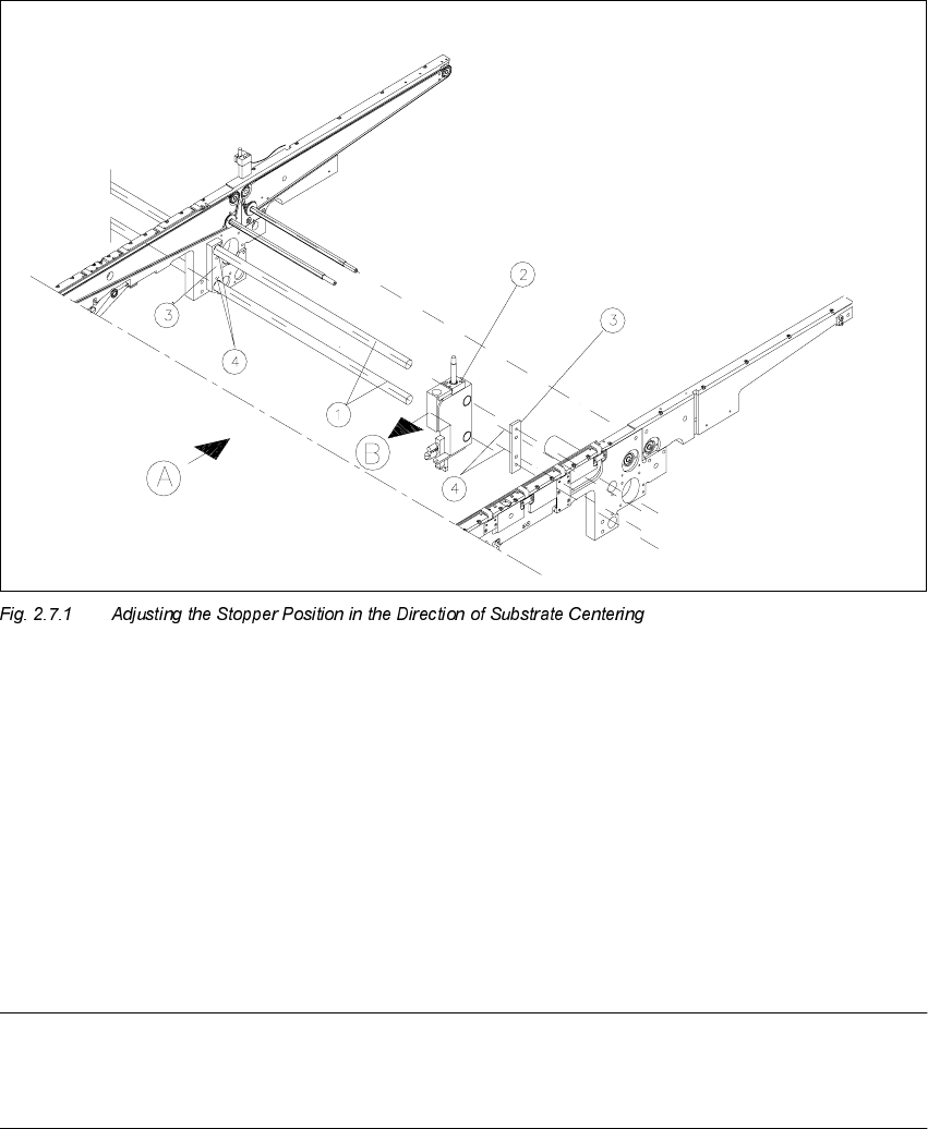
$GMXVWLQJWK H6WRSSHU3RVLWLRQ
.H\
A) PCB / substrate transport direction
B) Direction for adjusting the postion of the stopper
1. Stopper axles (on dual conveyor: continuous axles for belt 2)
2. Stopper assembly
3. Connection rail on fixed and movable side of the conveyor
4. Fastening for the connection rails: 2 socket hex head cap screws M4
NOTE:
As shown below, the substrate edge pointing toward the unloader must still be 0.5 mm IN FRONT
OF that of the unmovable roller of the fixed stop while the centering unit is open.