00192299-02.pdf - 第81页
SIPLACE HS-50 2 Retrofitting Instructions: Mechanical Ceramic Subs trate Centering HS-50 01/01 Issue 2.5 Sequence of Retrofitting 81 $V VHPEOLQJWKH&H UDPLF6XEVW UDWH &HQWHULQJ8QLW Å Install t he mechan…

2 Retrofitting Instructions: Mechanical Ceramic Substrate Centering HS-50 SIPLACE HS-50
2.5 Sequence of Retrofitting 01/01 Issue
80
,QVWDOOLQJWKH/LIWLQJ7D EOH
CAUTION
During the subsequent installation of the lifting table plate there is a slight risk of fingers and hands
being pinched, crushed or cut off, e.g., between the outer edges of the lifting table plate and the
conveyor assemblies.
Å If a dual conveyor is installed, restore the conveyor to maximum width by moving the toothed
belt of the conveyor width adjustment assy to maximum width.
During this process, exert just a little force and do so only in the direction in which the toothed
belt is moving.
Å Make certain that the transmission lever on the pertinent lifting table motor is folded down on
the lifting curve.
Å Holding the lifting table with both hands, place it into the guiding tubes with the guide pillars
vertical.
Å Let the lifting table plate slide down slowly.
Å Check whether the lifting table plate is completely seated on the lifting curve.
Å Install the pertinent ball bearing on each rocking lever (see Fig. 2.5.2 -> 2).
While doing so, put the spacer disk back in.
SIPLACE HS-50 2 Retrofitting Instructions: Mechanical Ceramic Substrate Centering HS-50
01/01 Issue 2.5 Sequence of Retrofitting
81
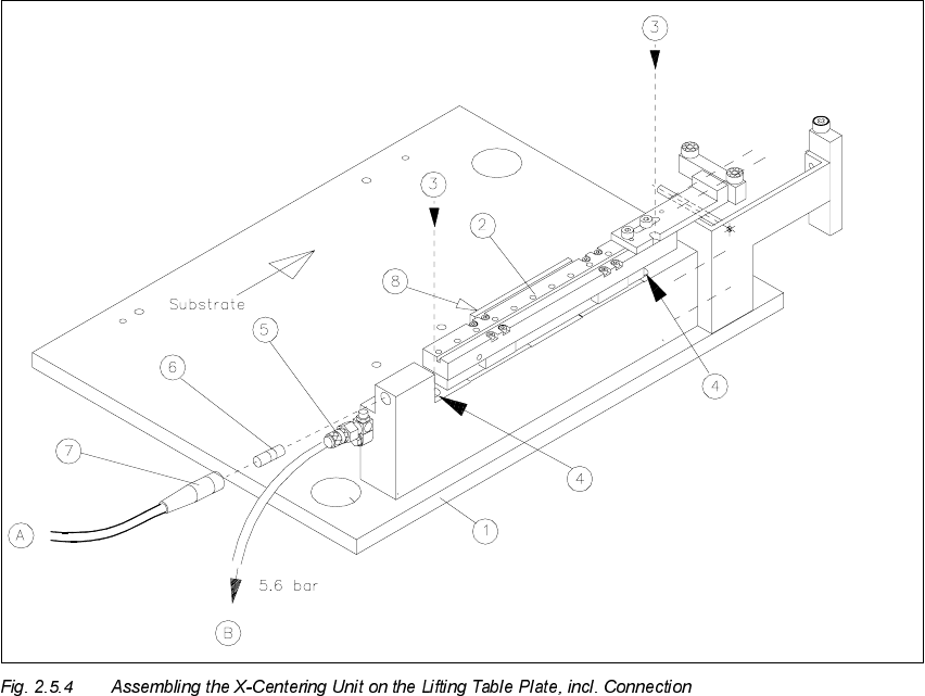
$V VHPEOLQJWKH&H UDPLF6XEVW UDWH &HQWHULQJ8QLW
Å Install the mechanical ceramic substrate centering unit on the fixed conveyor side.
The pins on the bottom of the body of this unit have to fit into the centering holes in the lifting
table plate.
.H\
1. Lifting table plate
2. Mechanical ceramic substrate centering unit
3. 2 socket hex head cap screws M4 x 45
4. Holes for fastening screws (in the body of the centering unit)
5. Connection for pneumatic hose and restrictor (opening speed)
6. Proximity switch
7. Proximity switch cable with connector
8. Flat cylinder of compressed air, with tension spring
Å Move the X-slide unit such that the holes in the body of the centering unit are accessible one
after the other.

2 Retrofitting Instructions: Mechanical Ceramic Substrate Centering HS-50 SIPLACE HS-50
2.5 Sequence of Retrofitting 01/01 Issue
82
During this process, insert the 2 socket hex head cap screws M4 x 45 from above (see Fig.
2.5.4 -> 3, 4).
Å Use them to bolt the body of the centering unit onto the lifting table.
Å Adapt the X-centering unit to the substrate size to be handled next (see Section 2.5.9).
6HWWLQJWKH2SHUDWLQJ'LVWDQFHRIWKH3UR[LPLW\6ZLWFK
Å Make certain that the operating surface of the inductive proximity switch is set 0.2 mm back
from the stop surface of the slide unit in the hole.
This precludes the possibility that the proximity switch might serve as a stop during the opening
movement and being damaged as a result.
Å If necessary, correct the position of the proximity switch (grub screw, size 1 Allen wrench).
The proximity switch has an LED for checking the switching process.
$GDSWLQJWRWKH6XEVWUDWH6L]H
To ensure the 3-point contact of the substrate for the centering unit in the X-direction, the ceramic
substrate centering unit has to be adapted to the substrate size to be processed afterwards.
To do this, install the pertinent stop rail (with 2 ball bearings) and the pertinent stop unit (with sta-
tionary roller AND distance bolt) -> Item no. see table below.
CAUTION
The distance bolt ist not to remove ! .
Designation For substrate width Item no.
Stop rail 1 assembly
with parallel pin
for 50 mm to 62 mm 00358877-01
Stop rail 2 assembly for > 62 mm to 106 mm 00358884-01
Stop rail 3 assembly for > 106 mm to 140 mm 00358885-01
Stop unit kit 1 (complete
with distance bolt)
for 50 mm to 62 mm 00358874-01
Stop unit kit 2 (complete
with distance bolt)
for > 62 mm to 106 mm 00358875-01
Stop unit kit 3 (complete
with distance bolt)
for > 106 mm to 140 mm 00358876-01