4OM-996-007.pdf - 第207页
3. T roubleshooting after Error Window (Error ID) Assuming "Error ID", "Item (Error Name)", and "Description" in the "ER- ROR" window as an index, the system retrieves the related …
(a) When the "Warm Start" operation is feasible, the [WARM] button
appears in the "OPN. MODE" window (submenu).
(b) When the [WARM] button is not displayed, it means that the "Warm
Start" operation is not feasible or there was a mistake in the re-
medial procedure after an error had occurred. In this case, per-
form the semi-automatic operation (step designation) to reset the
machine to its normal condition.
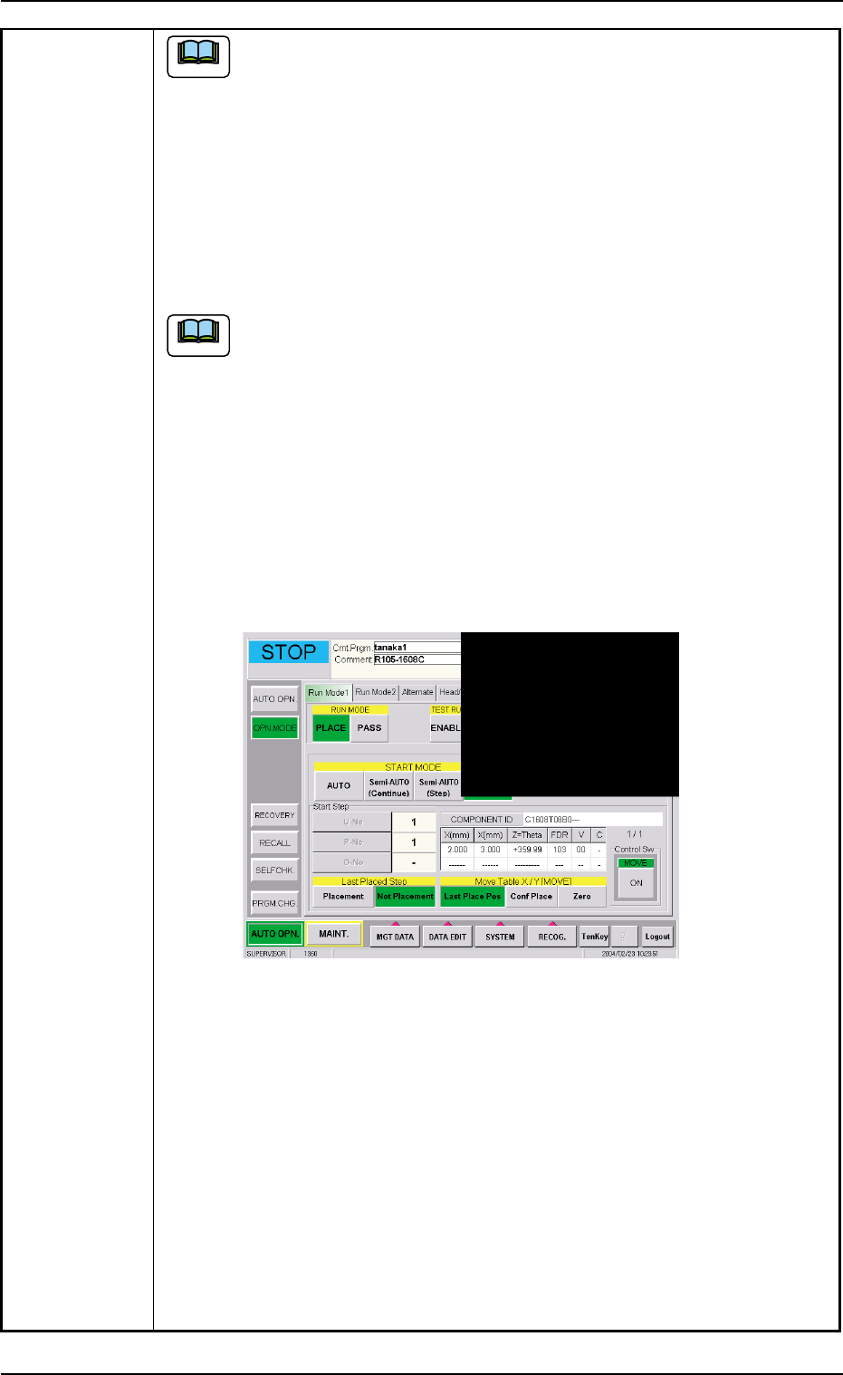
(8) Check how the last component was placed when the operation was inter-
rupted.
The last placement step is indicated in the "Start Step" group box in
the "OPN. MODE" window (submenu).
Check visually whether or not the relevant component is placed on
the P.C.B.
(9) Press the [Last Placed Pos.] button (entitled "Move Table X/Y") in the "OPN.
MODE" window (submenu).
(10) Press the [RECOG.] button on the main menu bar and make the recog-
nition window (1/4 of the whole view at the upper right corner) appear.
(11) Press the [ON] button (entitled "MOVE"). In two seconds, press the [EN-
ABLE] button on the operation panel.
The last placement position is displayed as a recognition image.
Fig. 4B16 "OPN. MODE" Window (Last Step Confirmation)
(12) Check whether or not the component is placed. If not, select the [Place-
ment] button. If the component is already placed, select the [Not Place-
ment] button.
(13) Press the [Zero] button (entitled "Move Table X/Y") and press the [ON]
button (entitled "MOVE"). In two seconds, press the [ENABLE] button on
the operation panel. The X/Y Table is zeroed.
(14) Press the [START] button on the operation panel. The "Warm Start" op-
eration is implemented.
(15) As for the P.C.B. produced through "Warm Start" operations, be sure to
confirm that all components are correctly placed.
Note
Note
0412-002 2-32 AIM01ETRP
2.4 Continuous Operation Disabled during Component Placement
3. Troubleshooting after Error Window (Error ID)
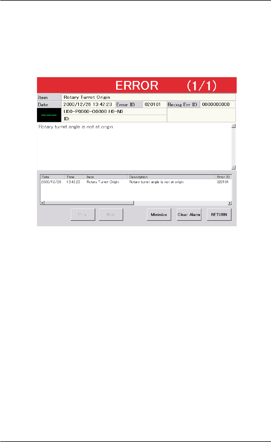
Assuming "Error ID", "Item (Error Name)", and "Description" in the "ER-
ROR" window as an index, the system retrieves the related page of the
instruction manual.
Refer to "3.1 Typical Description" for the detailed description.
Fig. 4B17 Example of "ERROR" Window
3. Troubleshooting after Error Window (Error ID)
0305-001 2-33 AIM01ETRP
3.1 Typical Description
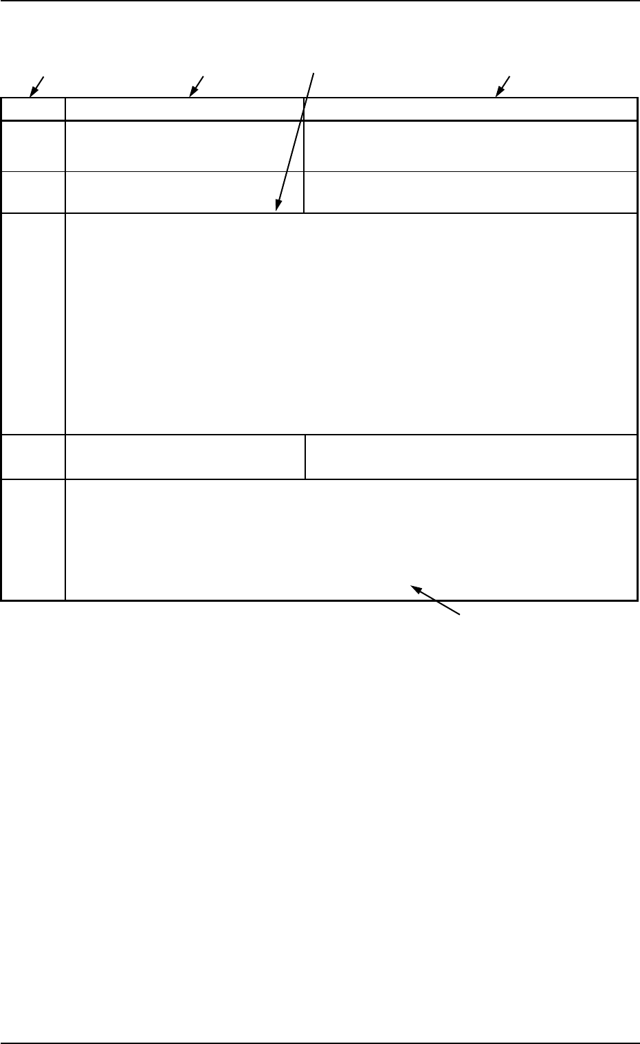
Table 4B8
Error ID Item Description
11040* L CONVEYOR WIDTH LIMIT (+) LIMIT ERROR HAS BEEN DETECTED.
; BPH77 E/NR
11040* L CONVEYOR WIDTH LIMIT (-) LIMIT ERROR HAS BEEN DETECTED.
; BPH77 E/NR
(Cause 1) An optical beam of the sensor is shielded.
(Cause 2) Dirt adheres to the sensor and the optical beam is shielded.
(Cause 3) The sensor is defective.
(Remedy 1) Turn off the power supply and move the conveyor width with the manual knob
for easier operation. Re-attach the light shield plate or the sensor securely (re-
move the looseness).
(Remedy 2) Wipe off dirt on the sensor and zero the L conveyor again.
(Remedy 3) Replace the sensor with a new one.
12010
* R CONVEYOR WIDTH ORIGIN OUTPUT SIGNAL FROM THE PULSE MOTOR
DRIVER WAS NOT DETECTED.
(Cause 1)
(Remedy 1)
(Continued to the next page)
*1 The error IDs (IDs displayed in the "ERROR" window) are described
in the numerical order.
"*" in the table will be filled with a numeric character.
*2 Described are the error name (item) and the description in the
"ERROR" window.
*3 Described are the causes and remedial procedures of the errors
in "*2 (Item and Description)".
The causes and remedies are correlated as follows.
(Cause 1)
ÆÆ
ÆÆ
Æ (Remedy 1)
(Cause 2)
ÆÆ
ÆÆ
Æ (Remedy 2)
(Cause 3)
ÆÆ
ÆÆ
Æ (Remedy 3)
*4 This indicates that the related contents are described subsequently
on the next page.
*4
*2
*3
*2
*1
3.1 Typical Description
0305-001 2-34 AIM01ETRP