4OM-996-007.pdf - 第29页
Safe-18 AIM01E-P Safety Precautions [Feeder Work Area Safety Door] Switches Each feeder work area safety door is provided with a [Feeder W ork Area Safety Door] switch inside as shown below . Fig. 1X18 [Feeder Work Area …
Safe-17 AIM01E-P
Safety Precautions
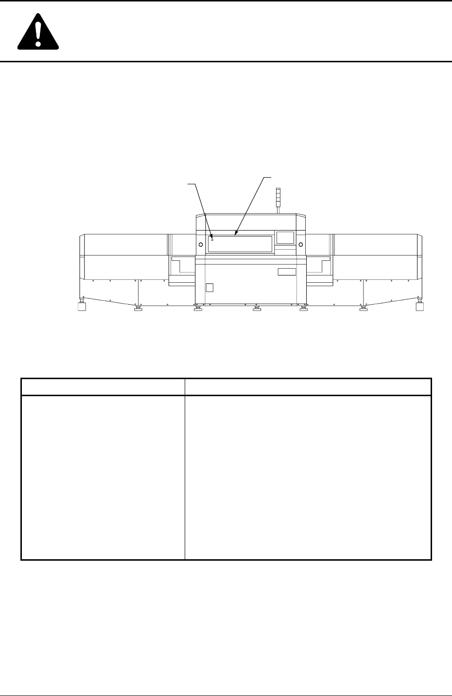
[Front Safety Door Check] Switch
When the front safety door is opened with the [OPERATION] switch set to "RUN", the
switch is activated and an error occurs.
When the switch is set to "SETUP", it is not activated.
Table 1X2
Switch Name Countermeasures
When the front safety door is opened, the following mea-
sures are taken.
• All power sources for loads are shut off.
The power supply to the mechanisms of all motor
shafts and 24-voltage loads in the solenoid system
(SOL and SV) is shut off.
Note: The load power supply for the vacuum pump
and the DD motor is excluded.
The control power supply for the control
boards and sensors is also excluded.
[Front Safety Door Check] Switch
[Front Safety Door Check] Switch
Front Safety Door
Fig. 1X16 Front View
0412-001
Safe-18 AIM01E-P
Safety Precautions
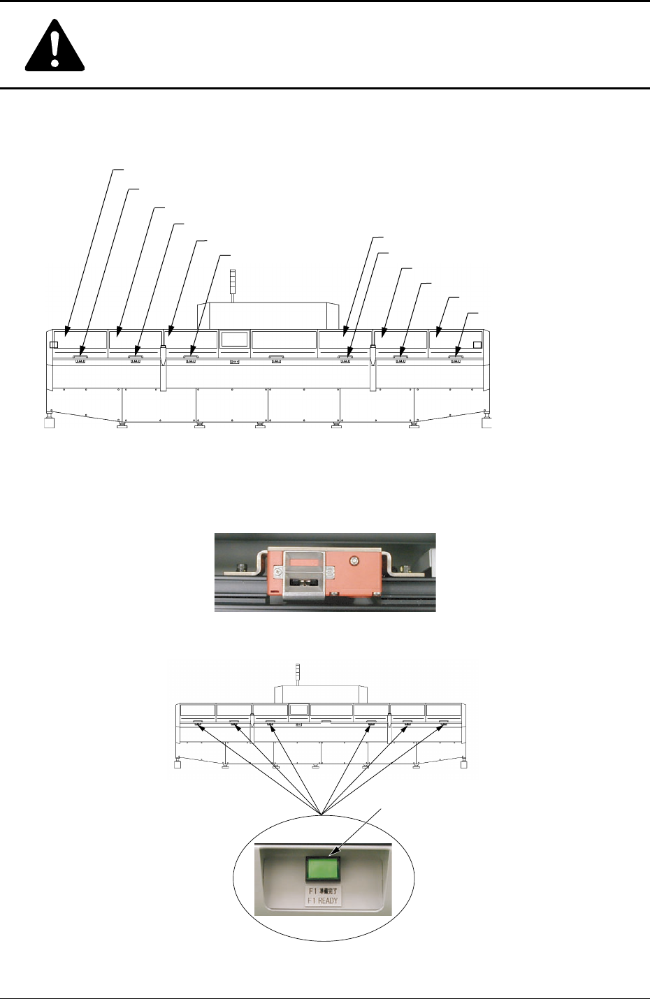
[Feeder Work Area Safety Door] Switches
Each feeder work area safety door is provided with a [Feeder Work Area Safety Door]
switch inside as shown below.
Fig. 1X18 [Feeder Work Area Safety Door] Switches
Fig. 1X19
F4 Work Area Safety Door
F3A Work Area Safety Door
F2B Work Area Safety Door
F3B Work Area Safety Door
F2A Work Area Safety Door
F1 Work Area Safety Door
[F4 Work Area Safety Door] Switch
Fig. 1X17 Rear View
[F3A Work Area Safety Door] Switch
[F2A Work Area
Safety Door] Switch
[F1 Work Area
Safety Door] Switch
[F2B Work Area Safety Door] Switch
[F3B Work Area Safety Door] Switch
[FEEDER READY] Buttons
0412-001
Safe-19 AIM01E-P
Safety Precautions
Table 1X3
Switch Name Countermeasures
(a) When the lamp of the [READY] button is "OFF", the [Work Area
Safety Door] switch is released, making it possible to supply
components.
Confirm that the lamp of the [FEEDER READY] button is "OFF"
and then open the safety door.
(b) When the machine is in the emergency stop mode (load power shut
off), the lamp of the [READY] button extinguishes and the electro-
magnetic lock of the work area safety door is released exception-
ally although the feeder carriage is not located in the work area.
[F1 Work Area Safety Door] Switch
[F2A Work Area Safety Door] Switch
[F3B Work Area Safety Door] Switch
[F2B Work Area Safety Door] Switch
[F3A Work Area Safety Door] Switch
[F4 Work Area Safety Door] Switch
• When the feeder carriage is located in the work
area and the work area safety door in the work
area is opened, the power to drive the feeder
carriage is shut off.
Ref.: The lamp of the [READY] button extin-
guishes.
• When the feeder carriage is not located in the
work area, the [Work Area Safety Door] switch
in the work area is activated, preventing the
safety door from being opened.
Ref.: The lamp of the [READY] button
illuminates.
Should the safety door opens at this time,
the power to drive the feeder carriages (F1
through F4) is shut off.
• While the work area safety door is kept open,
the feeder carriage is prohibited from any move-
ment such as zeroing and manual alignment op-
erations, etc.
Note
0412-001