YC8_Mainte_E.pdf - 第67页
3-18 3 Periodic maintenance items 5 Reattach the filter cap. 1. Fit the filter into the filter cap and insert it into the ejector . 2. Using a precision slotted screwdriver , turn the filter cap clockwise to secure it. c…
3-17
3
Periodic maintenance items
3. Three-month inspection
3.1 Head
This section describes the maintenance procedures, using the V2 head machine as an example.
3.1.1 Cleaning and replacing the ejector filter
Although depending on the air supply conditions and operating time, ejectors should be inspected once every
3 months. Use an air blow tool to remove dust buildups when small. We recommend replacing the air filter if
heavy dust deposits are found.
n
Required tools
• Square cloth
• Precision slotted screwdriver (option)
• Tweezers
• Air blow tool (option)
• Replacement parts (See 2.1.1 “Consumable parts and replaceable parts (for repairs)” in Chapter 1.
c
n
NOTE
Before beginning the work, put a square cloth on the conveyor to prevent any parts from being lost or dropping into
other sections and causing trouble.
1
Move the head all the way to the
front end of the Y axis.
On the [Unit]-[Head] tab (or [conveyor] tab)
screen, press the [Axis] button to open the
"Move Axis" screen. Then move the head
assembly all the way to the front of the Y
axis (front of machine).
TIP
The ejector unit is located at the front of the head
assembly. It is easier to inspect the ejector filters when
the head assembly is positioned to the front side of the
Y axis. (Inspect the ejector filters from the front of the
machine.)
e
2
Press the emergency stop button.
The machine should be in emergency stop
to ensure safety during work.
3
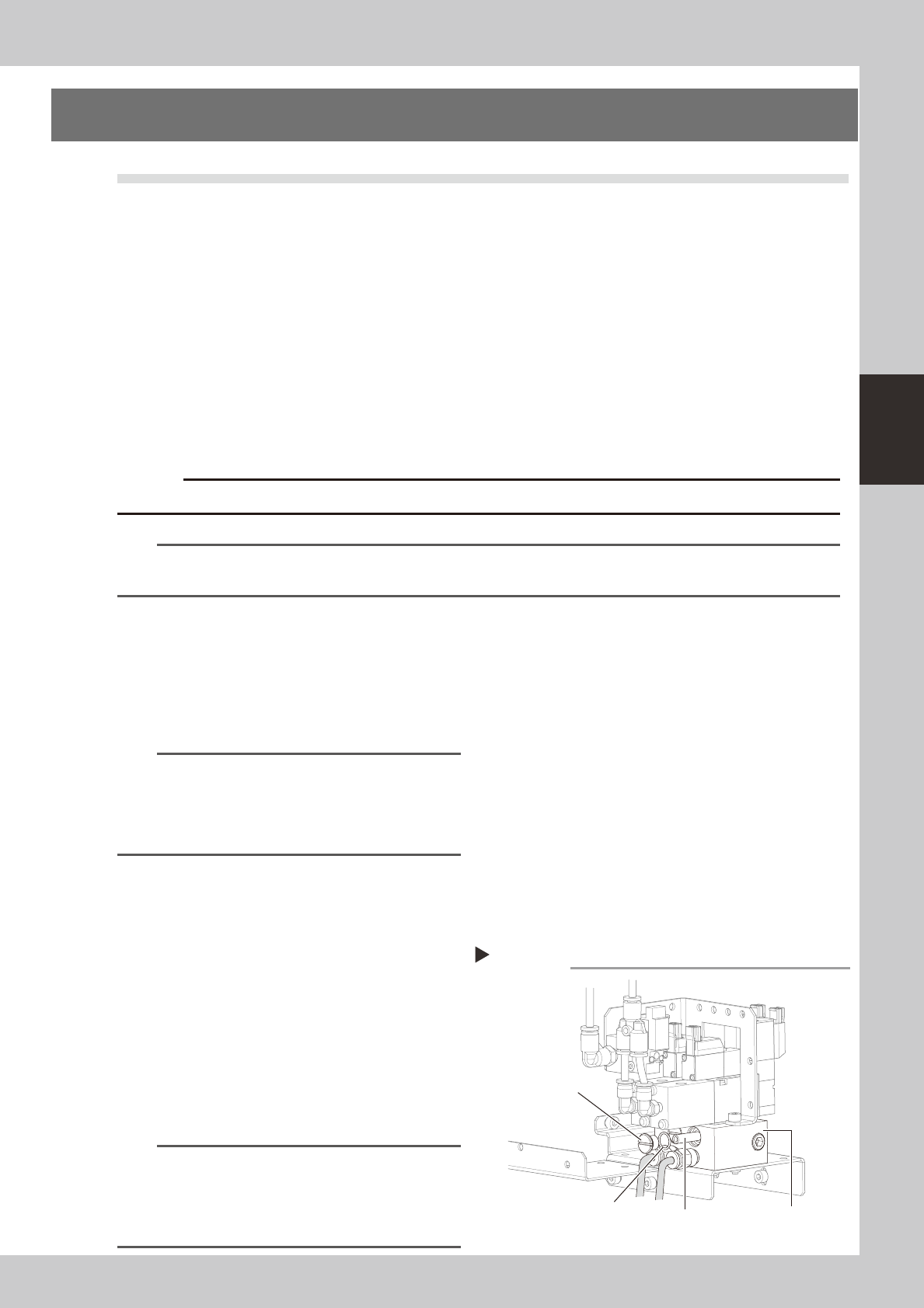
Remove the filter cap.
Loosen and remove the filter cap with a
slotted screwdriver.
53319-N8-00
4
Clean the filter.
Use tweezers to take the filter out of the
ejector. When there is only a little dust in the
filter, use an air blow tool to blow it away
and return the filter back to the original
position.
n
NOTE
If there are heavy dust deposits in the filter or the filter
has discolored, replace it with a new filter (K46-M8527-
C0X). As a general guide, filters should be replaced
once every 3 months, although this depends on the
actual operating time.
Removing the filter cap
Step 3
Ejector unit
Filter cap
O-ring
Filter
3-18
3
Periodic maintenance items
5
Reattach the filter cap.
1. Fit the filter into the filter cap and insert it
into the ejector.
2. Using a precision slotted screwdriver, turn
the filter cap clockwise to secure it.
c
3.1.2 Checking the ejector vacuum pressure
Check the vacuum level of each ejector of the ejector unit to see if it is working correctly.
c
Wear dust-proof goggles and mask to protect your face from blown air.
e
1
Press the emergency stop button.
The machine should be in emergency stop
to ensure safety during work.
2
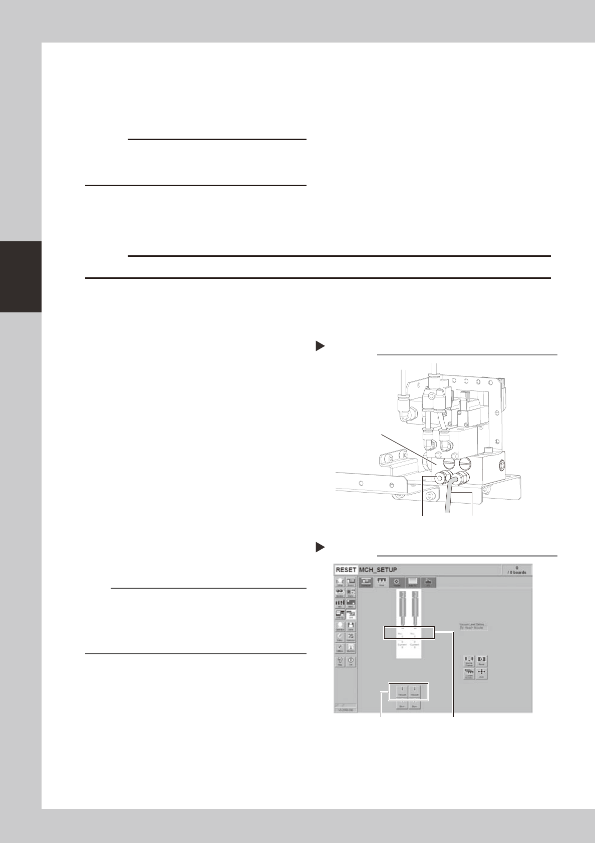
Disconnect the air hose from the
air joint under each ejector.
Disconnect all air hoses from the air joints (air
couplings).
53320-N8-00
3
Check the ejector vacuum level.
1. Open the [Unit]-[Head] tab.
2. Press the [Vacuum] button while blocking
each air joint with your finger.
3. Make a note of the "Max" reading of
each head while the air joint is blocked,
and check that the reading is higher
than the criterion value below.
Make the same check for all heads.
54306-N8-00
n
Criterion of ejector vacuum level
When air joint is blocked: 190 or more
TIP
If the vacuum level of any head does not reach the
criterion value, then check the air path in the head
(interior of the spline shaft or air hose between the
ejector and spline shaft). Clean or replace it if
necessary.
Disconnecting the air hoses
Step 2
Air hose
Air joint
Ejector unit
Checking the vacuum levels
Step 3
[Vacuum] button Check "Max" vacuum levels
(with air joint blocked).
3-19
3
Periodic maintenance items
3.1.3 Checking the blow valve operation (each head)
Check the blow level of each ejector of the ejector unit to see if it is working correctly.
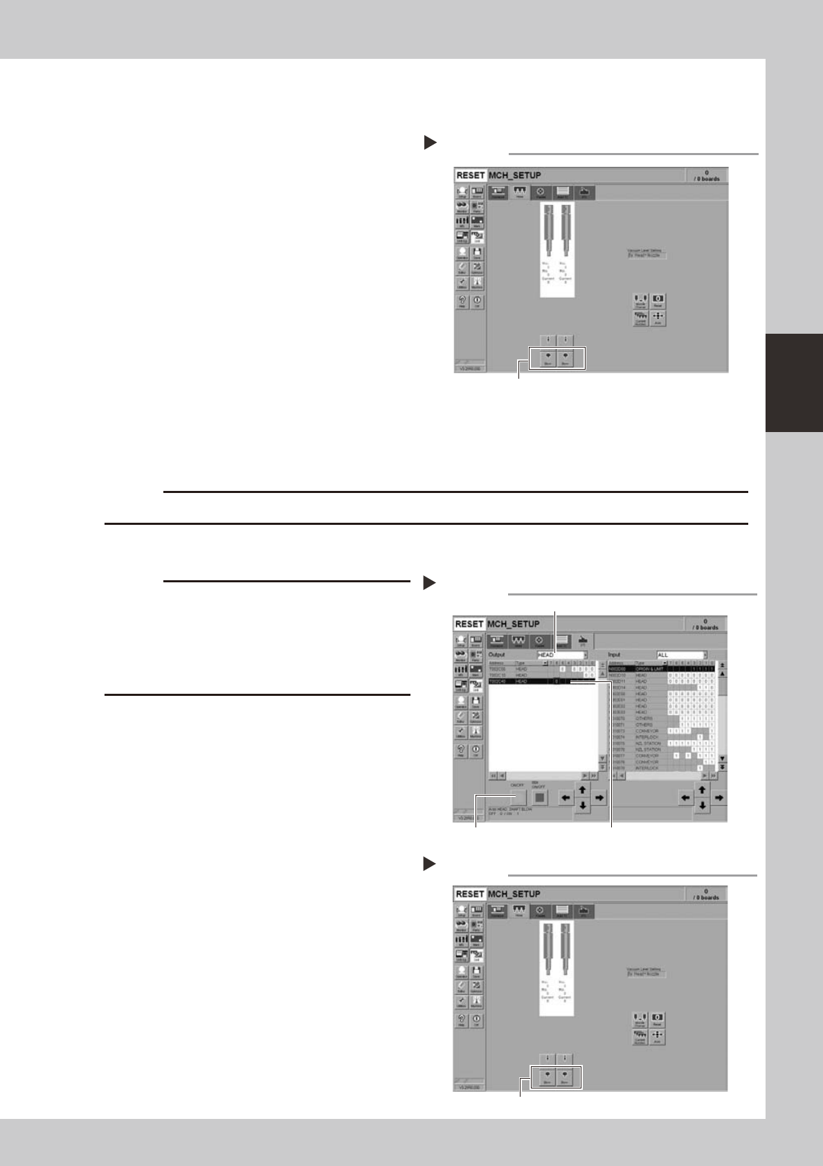
1
Check that the blow air is being
exhausted correctly.
To check if the blow air is being uniformly
exhausted from each air joint on the lower
part of the ejector unit, open the [Unit]-
[Head] tab and press the [Blow] button for
each head.
54307-N8-00
3.1.4 Checking the cleaning blow valve operation (for all heads)
Check that the cleaning blow function for the spline shafts is working correctly.
c
Wear dust-proof goggles and mask to protect your face from blown air.
1
Remove the nozzles from all heads.
c
A strong air flow is exhausted during the cleaning blow.
Always remove all nozzles attached to the heads before
starting the cleaning blow. Starting the cleaning blow
while the nozzles are still attached may blow the
nozzles away from the heads causing the nozzles to
break or become lost.
2
Operate the cleaning blow valves.
1. Open the [Unit]-[I/O] tab.
2. Select [Head] from the Output dropdown
list and select the address for the head
shaft blow (T003C000).
3. Press the [ON/OFF] button
to operate the
cleaning valves of all heads.
54308-N8-00
3
Check the exhaust blow air of each
head.
Open the [Unit]-[Head] tab. Press the [Blow]
button of each head to check the exhaust
blow air from each head.
54309-N8-00
4
Turn OFF the cleaning blow valves.
Checking the blow air exhaust
Press the [Blow] button for each head.
Step 1
Operating the cleaning blow valves.
Step 2
Press the [ON/OFF] button. Select Select an address.
Select a head.
Checking the blow air
Step 3
[Blow] button