YC8_Mainte_E.pdf - 第70页
3-21 3 Periodic maintenance items 5 Disconnect the air joint from the spline shaft. Fit the spanner (19) onto the bottom of the head so that the head will not move, remove the air joint with the spanner (8). 53322-N8-00 …
3-20
3
Periodic maintenance items
3.1.5 Cleaning the inside of the spline shaft
Dust or grime may adhere to the air path of spline shafts and cause component pickup or mounting errors.
Although depending on the air supply condition and operating time, the inside of each spline shaft should be
cleaned once every 3 months.
c
n
Required tools
• Phillips screwdriver
• Spanner (8mm, 19)
• Cleaning kit (option)
• Isopropyl alcohol
•
Paper cup or tray
• Cleaning rag
• Air blow tool (option)
c
e
1
Make the preparations for the
work.
1. Press the emergency stop button to put
the machine in the emergency stop
state.
2. Move the head to a convenient position
for maintenance work.
2
Remove the nozzles from all heads.
Remove all nozzles by hand.
3
Remove the spring suspending the
spline shaft.
Unhook the spring from the hook pin by
hand.
4
Remove the R-axis cover.
1. Remove the air hose from air joint.
2. Remove the three mounting bolts with
the Phillips screwdriver and remove the
cover.
53321-N8-00
Removing the cover
Step 4
Air hose
Cover
Mounting bolt
Air joint
Spring
3-21
3
Periodic maintenance items
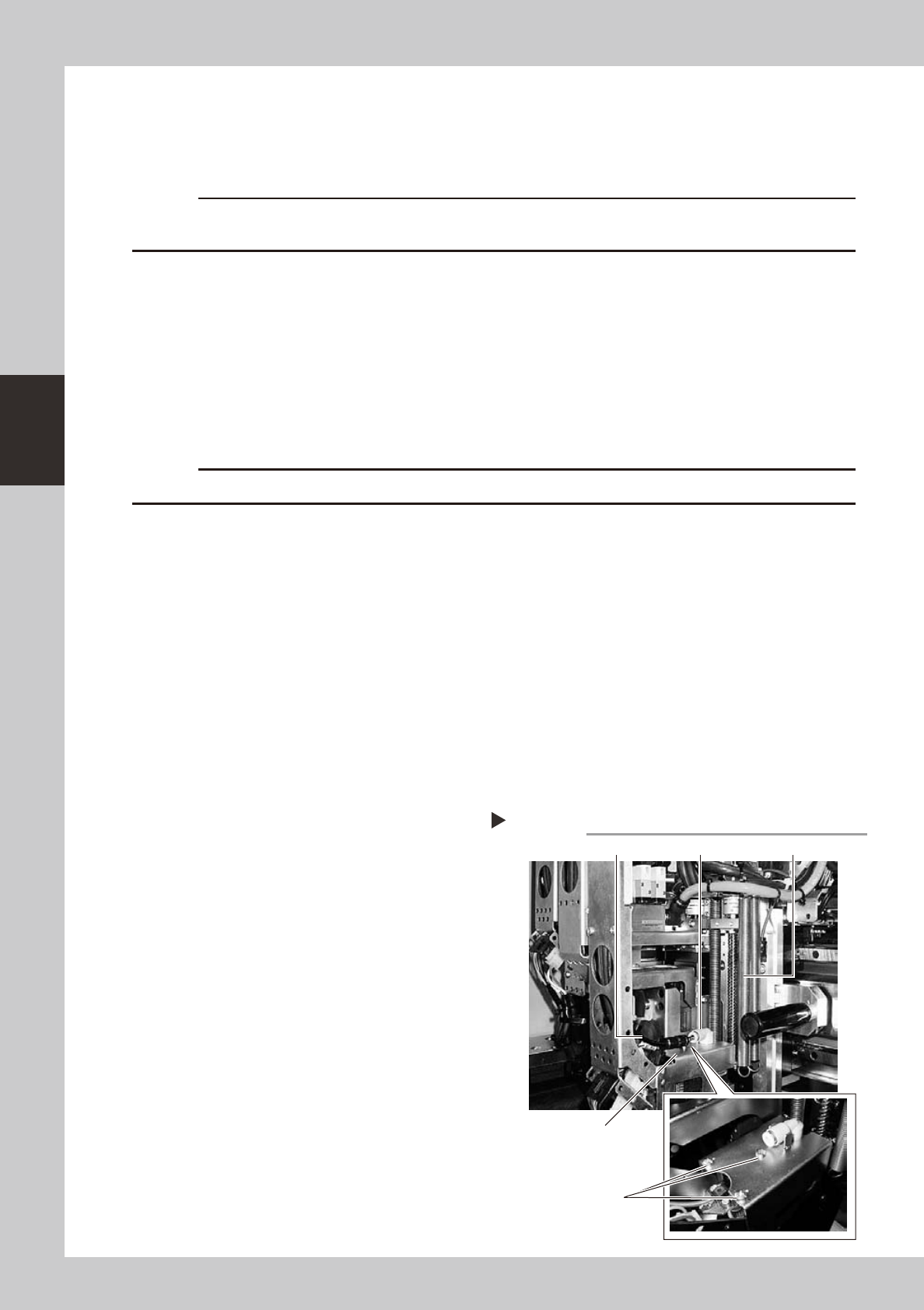
5
Disconnect the air joint from the
spline shaft.
Fit the spanner (19) onto the bottom of the
head so that the head will not move,
remove the air joint with the spanner (8).
53322-N8-00
6
Prepare the cleaning kit .
1. Pour Isopropyl alcohol into the container
of the cleaning kit.
2. Place a Paper cup or tray under the
spline shaft to be cleaned.
c
Never use solvent other than Isopropyl alcohol.
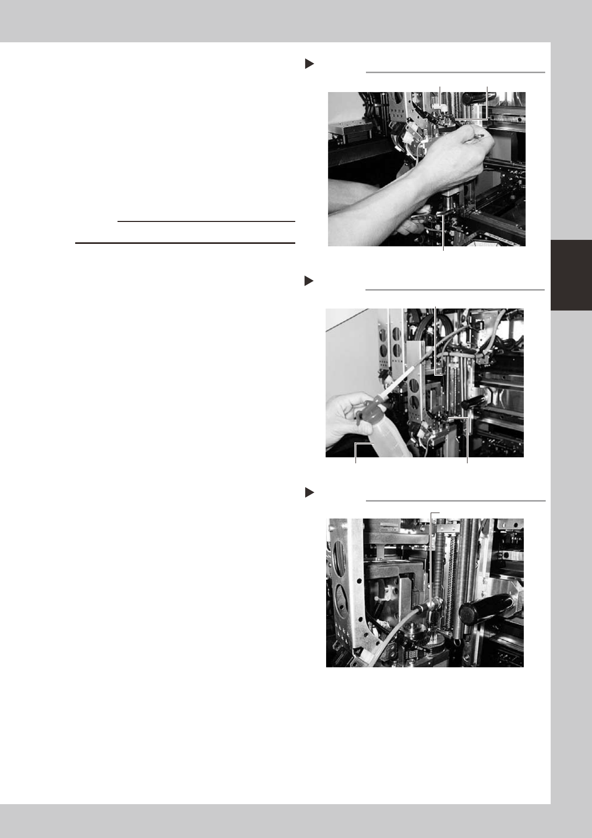
7
Clean the inside of the spline shaft.
1. Insert the nozzle of the cleaning kit into
the cleaning hole of the spline shaft.
2. Isopropyl alcohol into the spline shaft air
path to clean away dust and grime.
53323-N8-00
8
Blow air into the spline air path.
1. Connect the air blow tool to an air
connector on the front of the machine.
2. Use the air blow tool to blow air through
the spline shaft while placing a rag
against the tip of the spline shaft.
Repeat the above procedure (steps 7
and 8) until the Isopropyl alcohol flowing
out from the spline shaft becomes clean.
3. Make sure that after blowing air, smear
no longer appears on the rag placed
against the tip of the spline shaft, and
then reattach the ejector as in step 5.
53324-N8-00
9
Repeat the cleaning procedure.
Repeat steps 3 to 8 to clean the inside of
the spline shafts of all heads.
0
Return the head to its original
state.
Return the head to its original state in the
reverse order of steps 2 to 5.
Disconnect the air joint
Step 5
Use the spanner (19) to hold the head.
air joint spanner (8)
Cleaning the spline shaft
Step 6
Nozzle of cleaning kit
Spline shaftPump of cleaning kit
Air blow into spline shaft
Step 8
Air blow tool
3-22
3
Periodic maintenance items
3.1.6 Checking the negative pressure
After cleaning the spline shafts, check the negative pressure (vacuum level) generated in each head.
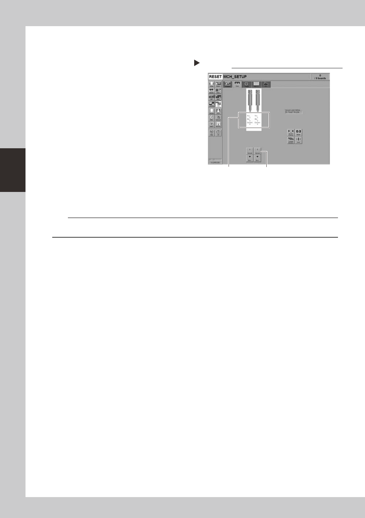
1
After assembly, check the vacuum
levels.
1. Leave nozzles detached from the heads.
2. Open the [Unit]-[Head] tab screen and
press the [Vacuum] button to generate a
negative pressure. Read the "Max" values
shown on the screen and determine
whether the vacuum levels are
appropriate by referring to the criteria
below.
54310-N8-10
2
Reattach the nozzles.
Attach the nozzles by hand back to the
heads.
n
Vacuum level criteria in spline air path
When nozzle is open : 70 or less
When nozzle is sealed : 190 or more
n
NOTE
The vacuum level in the spline shaft air path might sometimes differ slightly depending on the air source and operating
conditions. Use the above criteria for reference during maintenance.
Checking the vacuum level
Step 1
[Vacuum] buttonRead "Max" values.