YC8_Mainte_E.pdf - 第92页
Appendix Appendix Contents 1. Specifications A- 1 1.1 Air regulator unit A- 1 1.2 Power connection terminals A- 2 1.3 Connection between machines A- 3 1.3.1 PREVIOUS INTERF ACE connector A- 3 1.3.2 NEXT INTERF ACE connec…
5-7
5
How to replace consumable parts
5
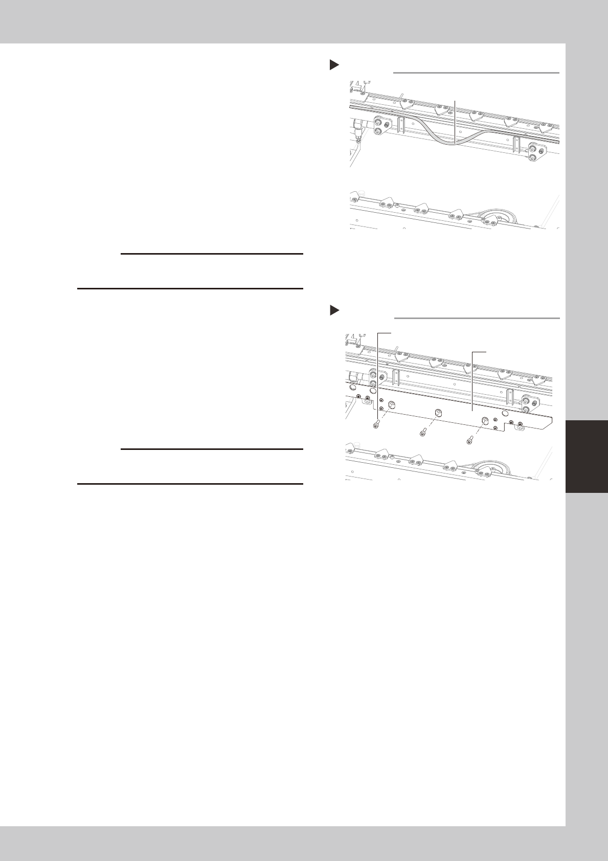
Detach the belt from the conveyor.
After you have detached the belt, clean the
clearance between the conveyor frame
and board guide with a fine brush or cloth
rag.
53513-N8-00
6
Attach a new belt.
1. Temporarily fit a new belt onto the pulley.
2. Reconnect the shaft to the pulley and
tighten the bolt.
3. Tighten the belt tensioner bolt while
applying a proper tension to the belt by
moving the belt tensioner bolt.
c
7
Reattach the board clamp assembly.
1. Install the board clamp assembly in the
original position and temporarily tighten
the bolts to secure the board clamp
assembly.
2. On the [Unit] – [Conveyor] tab, press the
[Board Clamp] button to raise the board
clamp assembly and tighten the bolts
securely.
53514-N8-00
c
and the board clamp raised.
8
Check the belt rotating condition.
1. Open the [Unit]-[Conveyor] tab, and
press the [Board Clamp] button again to
unclamp.
2. On the [Unit]-[Conveyor] tab, press the
[Conveyor In] button or [Conveyor Out]
button to turn on the conveyor motor
and check the belt rotation.
3. If the rotation speed fluctuates or there is
slack in the belt, adjust the position of the
tensioner bolt and then check the
rotation again.
Detaching the belt from the conveyor
Step 5
Belt
Installing the board clamp assembly
Step 7
Board clamp assembly
Mounting bolt (3 places)

A-1
Appendix
1. Specifications
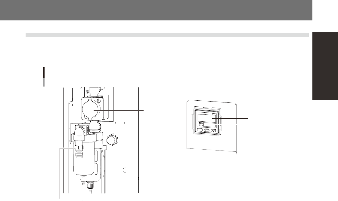
1.1 Air regulator unit
The air regulator for controlling the air pressure to the pneumatic units of the machine is located behind the
front lower left panel. A digital pressure gauge is provided on the front left of the machine. The air pressure
must be set to the optimum level.
Source air connector
Air regulator unit
Air supply/shutoff
switch (valve)
Air pressure regulator
Air pressure setting
for machine
Pressure-drop
detection level
53A01-N8-00
n
Supply air pressure
This is the pressure of the source air supplied to the machine. Before setting the air pressure with the air regulator, make
sure that this supply air pressure is in the following optimal range.
YC8 : 0.45MPa
n
Air pressure setting and pressure-drop detection level
Air pressure setting for machine (upper reading) : 0.40MPa to 0.41MPa
Pressure-drop detection level (lower reading) : 0.33MPa
n
Digital pressure gauge
Shows the supply air pressure (upper reading) and pressure-drop detection level (lower reading). A normal pressure value
is shown in green, and a pressure value lower than the pressure-drop detection level is shown in red.
n
Air supply/shutoff switch (valve)
Turning this switch to the right shuts off air supply and exhausts air that remains inside the machine.
n
Source air connector
Prepare an air hose with an inner diameter of at least 8mm having a 40SH socket (Nitto Koki, or equivalent), and connect
it to this connector. Use dry, clean air passed through an air filter.