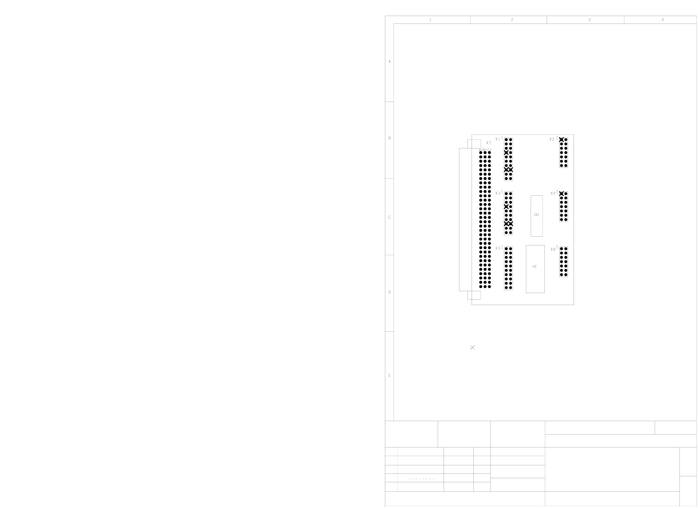
S25 circuit.pdf - 第142页
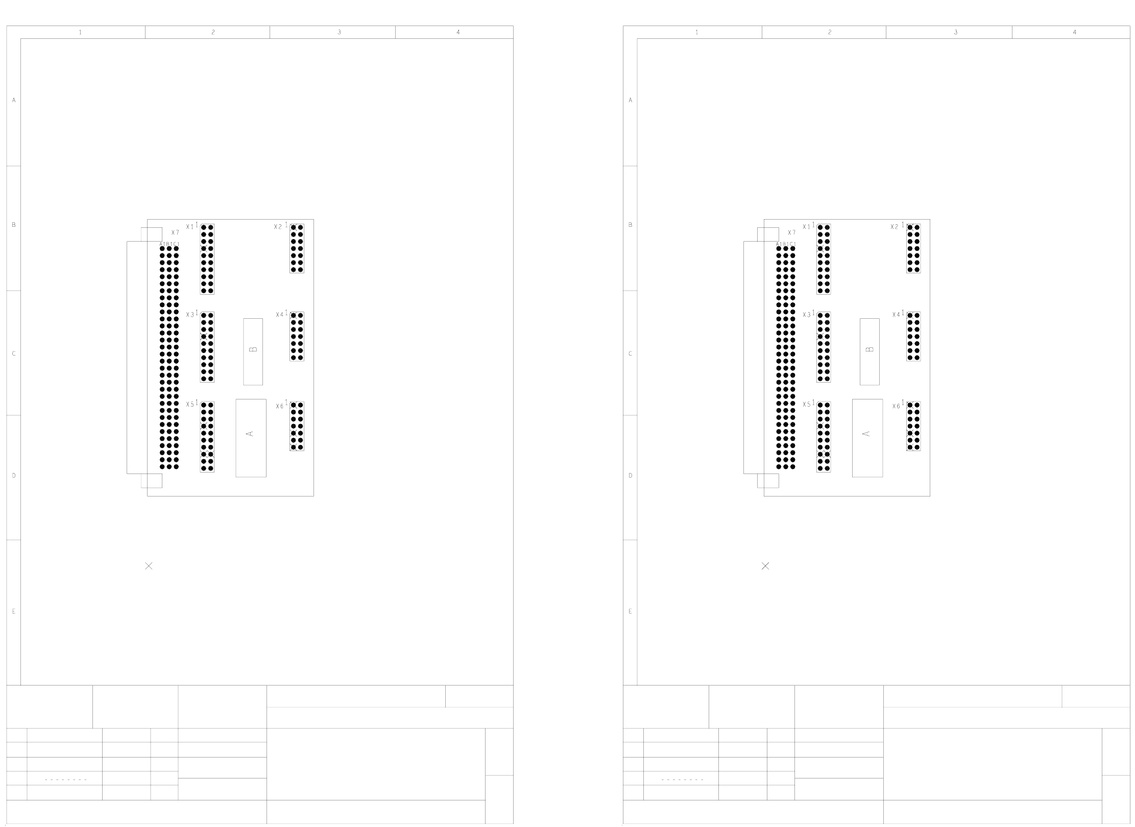
5 Printed circuit boar ds 142 0034605 7-010 101ND 4 854 P CB, S2 5 axi s rear panel for Z/DP , type I I M 1:1 A: Iden tifica tion label B: I nsp ect ion labe l Key: Pi nch off pins 2-laye r printe d circu it bo ard Compo…
5 Printed circuit boards 141
00345015-010101ND4 854 PCB, S25 axis rear panel for X/Y/star
00345016-010101ND4 854 PCB, S25 axis rear panel for Z/DP
01
Zust. Mitteilung Datum
15.01.99 KL
Name
SIEMENS AG
ATD TD MCH 2
KLOSE
11.01.99Datum
Name
00345015-010101ND4
G32918-K0083-B001-*-0017
for X/Y/star
S23 axis rear panel
2-layer printed circuit board
M 1:1
Sheet
1-
854 printed circuit board
Component layout, component side
A: Identification label
B: Inspection label
Key: Pinch off pins
5 Printed circuit boards 142
00346057-010101ND4 854 PCB, S25 axis rear panel for Z/DP, type II
M 1:1
A: Identification label
B: Inspection label
Key: Pinch off pins
2-layer printed circuit board
Component diagram, component side
854 printed circuit board
S23 axis rear panel
for Z/DP axes, type II
G32918-K0083-B001-*-0017
00346057-010101ND4
Shee
t
1-
SIEMENS AG
ATD TD MCH 2
KLOSE
10.02.99Datum
Name
KL
NameDatum
10.02.99
MitteilungZust.
01
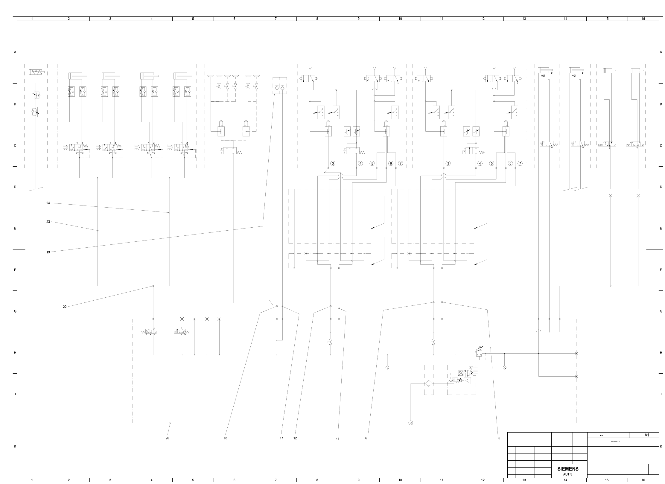
6 Pneumatic diagrams 143
6 Pneumatic diagrams
00341199-010302XD1 S25 pneumatic diagram
ES 03 10707 PUN4 PipW 09.05.01 De.
ES 02 9955 Abschaltvent. 19.09.00 De.
FS 01 S23 neu 26.11.98 De.
1
US 02 8595 Korr. Hick 06.05.99 De.
US 03 9462 Vakuum-Tool 28.10.99 De.
US 02 AEM 10960 03.09.01 Fu.
Weitergabe sowie Vervielfaeltigung dieser Unterlage, Verwer-
tung und Mitteilung ihres Inhalts nicht gestattet, soweit nicht
ausdruecklich zugestanden. Zuwiderhandlungen verpflichten zu
Schadenersatz. Alle Rechte fuer den Fall der Patenterteilung
oder GM-Eintragung vorbehalten.
Copying of this document, and giving it to others and the use
or communication of the contents thereof, are forbidden with-
out expreB authority. Offenders are liable to the payment of
damages. All rights are reserved in the event of the grant of
a patent or the registration of a utility model or design.
FS ES US UA S F
Debatin26.11.98
SIPLACE
00341199-010302XD1
B1
B2
B3
B4
B5
B6
B9
B8
B7
B10
B11
B12
B13
B14
B15
PUN6/1900
PUN6/2600
EZH-2,5/9-10
PUN8/2400
PUN8/2400
A2
A1
A4
A5
A3
A6
A7
E3
E2
E1
A2
A1
A4
A5
A3
A6
A7
E3
E2
E1
PUN8/1200
PUN8/1200
PU3/2800
PU3/2800
PUN4/1700
PUN4/2900
YJ1
B16
PUN6/1500
PUN6/2600
Portal 2
PU4/1500
medium
Dimensional variations:
Degree of accuracy
acc. to ISO 2768 mH
(Material, semifinished products)
(Unmachined part no.)
(Model or swage no.)
Scale
Format
Author
Check.
Stand.
Status Modified Date Name
Main no.
(Drawing number) Sheet
Sh.
S25 pneumatic diagram
Date
Name
p = 2.5 ± 0.2 bar
Gantry 1
p = 5.2 ± 0.1 bar
p = 5.5 to 8 bar
p = 2.5 ± 0.2 bar
internal
external
digital
8 Bit
NOMINAL value
7-fold hose - 1
7-fold hose - 2
7-fold hose - 4
7-fold hose - 5
7-fold hose - 3
7-fold hose - 6
7-fold hose - 7
Trailing cable
for gantry 2
Distributor for
Gantry 2
7-fold hose - 1
7-fold hose - 2
7-fold hose - 5
7-fold hose - 3
7-fold hose - 4
7-fold hose - 6
7-fold hose - 7
for gantry 1
Trailing cable
Gantry 1
Distributor for
5.1 bar
5.1 bar
(righth. side) (lefth. side)
PCB stopper
(Option)
PCB stopper
changer
Nozzle
changer
Nozzle
Reject
circuit
nozzle dia. 1mm
nozzle dia. 1.5mmnozzle dia. 1.5mm
Holding circuit
Forced air
Forced air
Placement circuit
Holding circuit
Forced air
Forced air
Reject
circuit
Speed-Placer 6-12Speed-Placer 6-12
nozzle dia. 1mm
Placement circuit
Feeder
lefth. side
righth. side
Table
(Option)
Table
Connecting
Bulk case
Vacuum tooling
(Option)
Ø 40 ; stroke 30
(Option) lefth. side righth. side
centering
Substrate
pneumatically operated
Tape cutter
pneumatically operated
Tape cutter
Ø 40 ; stroke 30Ø 40 ; stroke 30Ø 40 ; stroke 30
Valve 1 Valve 2 Valve 1 Valve 2
p = 5.2 ± 0.1 bar
Cyl.1 Cyl.2 Cyl.1 Cyl.2