S25 circuit.pdf - 第68页
3 Circ uit d iagrams 68 0035621 3-010 101FD4 S25 H M cont rol unit, basic module (Wrap con necti ons) (Sh . 1 of 3 ) 0035621 3-010 101FD4 S25 H M cont rol unit, basic module (Wrap con necti ons) (Sh . 2 of 3 ) S i e m e …
3 Circuit diagrams 67
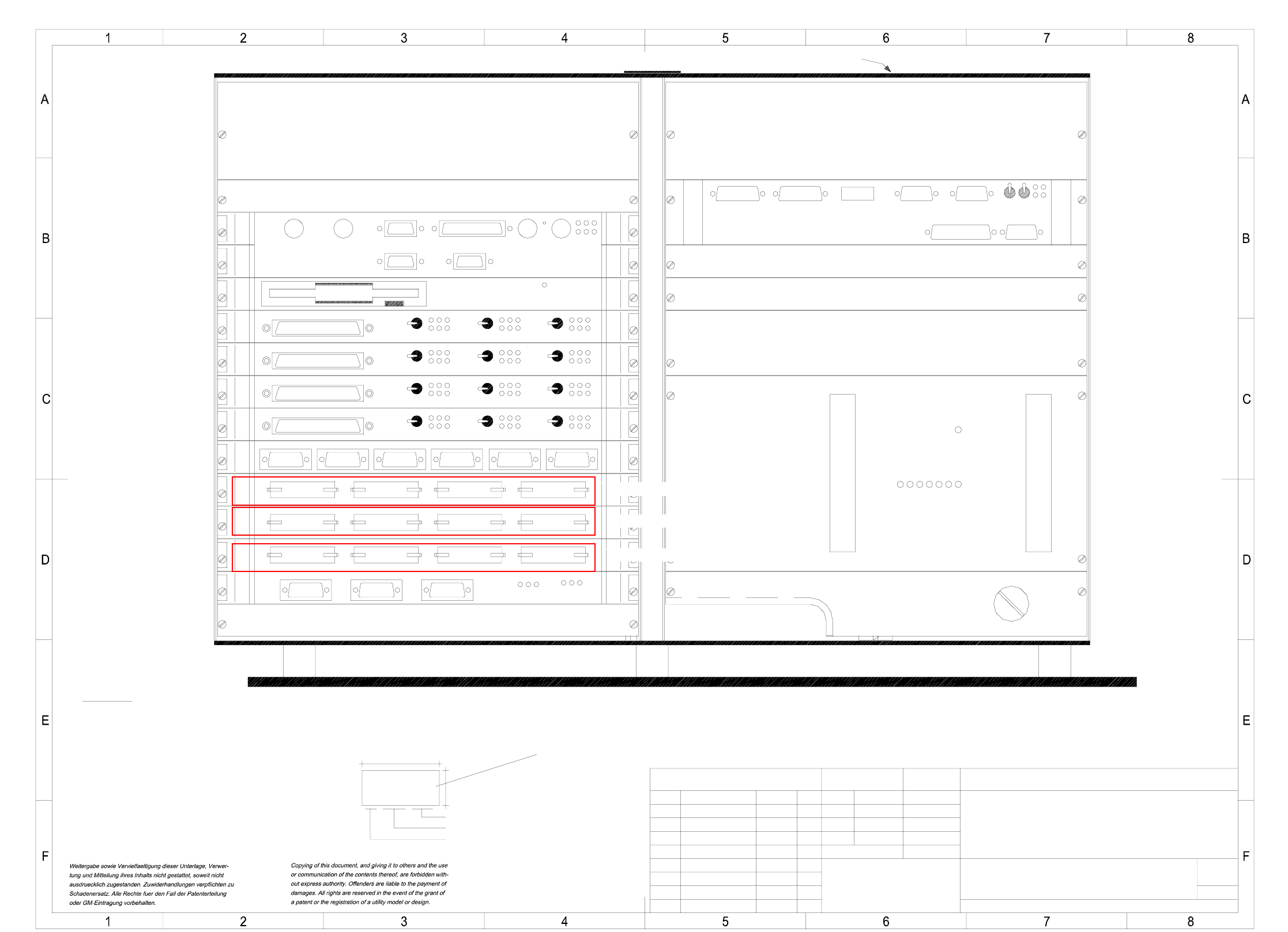
00356211-010101TD3 S25 HM control unit (viewed from the front)
(Zeichnungsnummer)
Norm
Gepr.
Bearb.
Datum
Name
NameDatumMitteilungZustand
PL EA 1 E2
SIEMENS
Stamm-Nr. FS ES US UA S F
Document status
Product status
Function status
Sh.
Sheet
SMD Placement System SIPLACE S25-HM
21.06.00
(viewed from the front)
A3
1
1:2Massstab
01.
15.06.2000 Tekin
15.06.00
15.06.00
27.06.00
Tek
Tek
Tek
01.
01.
S25-HM control unit
00356211-010101TD3
1
Mouse
Keyboard
COM-1COM-2
PrinterVGA
LAN1 LAN2
X4sa
X6sa
X11 X12 X7sa
X5sa
X10 X3
X3sn
Servo
OFF
Servo
OFF
OFF
Servo
Servo
OFF
OFF
Servo
OFF
Servo
X3tq
X3tr
Servo
OFF
Servo
OFF
OFF
Servo
X5sf X4sf X3sf X2sf
X2seX3seX4seX5se
Servo
OFF
OFF
Servo
OFF
Servo
X3sm
Harddisk
Floppy
GND
+24V
-15V
+15V
-12V
+12V
+5V
Fail
Battery
3.8V
S-COM 1S-COM 2
Camera 2/4 Camera 1/3
AUX VGA HS3L
X4scX3sc
X6scX7sc
X8scX5scX9sc
Abort
Reset
BARCODE
X5ty
BOOT
X4ty
CAN
X3ty
(ty)assembly A37
TSP-210
Function status (FS) according to the current parts list
Spare
Spare
S23 power supply unit
(ss)assembly A26
(te)assembly A19
coplanarity module
Reserved for
(sc)assembly A2
MVS340 vision module
Spare
Spare
Spare
(td)assembly A18
video multiplexer
Reserved for
(sa)assembly A1
Machine controller M54
(th)
assembly A11
Winchester/floppy M54
Spare
(sg)assembly A5
I/O board
(sf)assembly A4
I/O board
(se)assembly A3
I/O board
(sd)assembly A13
Communications assembly
Fan unit A35 (ue)
* Note
Reserved for
(sn)
assembly A7
(sm)
assembly A6
(tr)assembly A9
Axis board 1 x AC
(tq)assembly A8
(tc)assembly A17
Winchester/floppy GEM
(sb)
assembly A12
machine controller GEM
Axis board
Axis board
Axis board 1 x AC
Reserved for
* Note
Apply the following labels on the out side (flush with the front plate):
A: Identification label Assembly inscription according to VA-F-610-001
Font size 2.5 mm, material Scotchal 3698-E (color Al RAL 9006)
B: Inspection label Identification: Testing engineer, month, year
SIEMENS PL EA
00356211 / FS
AA-BBBB-CCCC
Series number
Date (year/month/day) acc. to SN 01007
Manufacturer/location acc. to SN 37040
40
18
Please note:
- Cover up plugs which are not used with metal caps, item no. 00354066.
- Connect the inside of the cable harness coating to the housing.
X2sgX3sgX4sgX5sg
S-COM 1
X2sd
S-COM 2
X3sd
S-COM 3
X4sd
S-COM 4
X5sd
CAN bus
X6sd
CAN bus
X7sd
S
ee page 52
S
ee page 52
S
ee page 53
3 Circuit diagrams 68
00356213-010101FD4 S25 HM control unit, basic module (Wrap connections) (Sh. 1 of 3)
00356213-010101FD4 S25 HM control unit, basic module (Wrap connections) (Sh. 2 of 3)
Siemens AG
Wrap connections
Drawing number: 00356213-010101FD4
Designation: S25-HM control unit, base
PLEA 1 E2
Responsible : PLEA 1 E6 Ref
Wollgarten
Signature Test department Development department Page 1 of 3
Date 28.02.01
S23 Control Unit, Wrap connections incl. M54
(AMS bus with 7 slots)
Coding, axis board 1 (SP3):
Axis no. 0 (module 1)
Axis no. 1 (module 2)
Axis no. 2 (module 3)
SMP-SP3 connection:
B7
⇔
B16
⇔
B19
Coding, axis board 2 (SP4):
Axis no. 3 (module 1)
Axis no. 4 (module 2)
Axis no. 5 (module 3)
SMP-SP4 connection :
B3
⇔
B4
⇔
B9
⇔
B16
⇔
B18
⇔
B20
Coding, axis board 3 (SP5):
Axis no. 6 (module 1)
Axis no. 7 (module 2)
Axis no. 8 (module 3)
SMP-SP5 connection :
B4
⇔
B5
⇔
B7
⇔
B8
⇔
B9
⇔
B16
⇔
B21
Coding, axis board 4 (SP6):
Axis no. 9 (module 1)
Axis no. 10 (module 2)
Axis no. 11 (module 3)
SMP-SP6 connection :
B3
⇔
B6
⇔
B8
⇔
B10
⇔
B16
⇔
B18
⇔
B19
⇔
B21
AMS interrupt axis boards
Connections:
AMS-SP6 / C7
⇔
SMP-SP3 / C15
⇔
SMP-SP3 / C17
⇔
SMP-SP3 / C19
⇔
⇔
SMP-
SP4 / C15
⇔
SMP-SP4 / C17
⇔
SMP-SP4 / C19
(AMS_INT2)
AMS-SP6 / A8
⇔
SMP-SP5 / C15
⇔
SMP-SP5 / C17
⇔
SMP-SP5 / C19
⇔
⇔
SMP-SP6 / C15
⇔
SMP-SP6 / C17
⇔
SMP-SP6 / C19
(AMS_INT3)
Coding for I/O boards 1 - 3 (SP8 - SP10):
Connections:
I/O board 1 SMP-SP8 / C31
⇔
SMP-SP8 / C23
⇔
⇔
SMP-SP8 / C25
⇔
SMP-SP8 / C27
I/O board 2 SMP-SP9 / C31
⇔
SMP-SP9 / C23
⇔
⇔
SMP-SP9 / C25
I/O board 3 SMP-SP10 / C31
⇔
SMP-SP10 / C23
⇔
⇔
SMP-SP10 / C27
Siemens AG
Wrap connections
Drawing number: 00356213-010101FD4
Designation: S25-HM control unit, base
PLEA 1 E2
Responsible : PLEA 1 E6 Ref
Wollgarten
Signature Test department Development department Page 2 of 3
Date 28.02.01
Communications assembly coding (SP7):
Connection:
SMP-SP7 / B15
⇔
SMP SP7 / B4
Communications assembly interrupts (SP12 and SP13):
Connections:
(COM 3) SMP-SP7 / C15
⇔
SMP-SP1 / C25 (SMP_INT5)
(COM 4) SMP-SP7 / C17
⇔
SMP-SP1 / C27 (SMP_INT6)
(COM 5) SMP-SP7 / C19
⇔
AMS-SP6 / B8 (AMS_INT4)
(COM 6) SMP-SP7 / C21
⇔
AMS-SP6 / C8 (AMS_INT5)
(CAN-Bus 1) SMP-SP7 / C23
⇔
AMS-SP6 / A7 (AMS_INT0)
(HS3L 1) SMP-SP7 / C25
⇔
AMS-SP6 / A9 (AMS_INT6)
E/As (P218) SMP-SP8 / C15
⇔
SMP-SP9 / C15
⇔
SMP-SP10 / C15
⇔
⇔
AMS-SP6 / B7 (AMS_INT1)
AMS bus:
Connections:
AMS-SP6 / A3
⇔
AMS-SP6 / B2 (bus priority)
AMS-SP6 / A4
⇔
AMS-SP2 / A3
AMS-SP6 / B5
⇔
AMS-SP5 / B5
⇔
AMS-SP2 / B5
⇔
AMS-SP1 / B5 (battery)
Axis CAN bus
Connections:
64-pin connector above SMP-SP7 (COM351) / A15
⇔
⇔
SMP-SP6 / C13
⇔
SMP-SP6 / C23
⇔
SMP-SP6 / C29
⇔
⇔
SMP-SP5 / C13
⇔
SMP-SP5 / C23
⇔
SMP-SP5 / C29
⇔
⇔
SMP-SP4 / C13
⇔
SMP-SP4 / C23
⇔
SMP-SP4 / C29
⇔
⇔
SMP-SP3 / C13
⇔
SMP-SP3 / C23
⇔
SMP-SP3 / C29
⇔
⇔
64-pin connector above SMP-SP7 (COM351) / B13
64-pin connector above SMP-SP7 (COM351) / A16
⇔
⇔
SMP-SP6 / B12
⇔
SMP-SP6 / C21
⇔
SMP-SP6 / C25
⇔
⇔
SMP-SP5 / B12
⇔
SMP-SP5 / C21
⇔
SMP-SP5 / C25
⇔
⇔
SMP-SP4 / B12
⇔
SMP-SP4 / C21
⇔
SMP-SP4 / C25
⇔
⇔
SMP-SP3 / B12
⇔
SMP-SP3 / C21
⇔
SMP-SP3 / C25
⇔
⇔
64-pin connector above SMP-SP7 (COM351) / B14
Interrupt TSP210 - MC :
Connection:
SMP-SP11 / B5
⇔
SMP-SP9 / B5
3 Circuit diagrams 69
00356213-010101FD4 S25 HM control unit, basic module (Wrap connections) (Sh. 3 of 3)
Siemens AG
Wrap connections
Drawing number: 00356213-010101FD4
Designation: S25-HM control unit, base
PLEA 1 E2
Responsible : PLEA 1 E6 Ref
Wollgarten
Signature Test department Development department Page 3 of 3
Date 28.02.01
Connection between communications assemblies and ICOS:
Flat ribbon cable, 20-pin
Communications assembly for rear panel X99 Kombgr Rückwand X99 (via SP7)
ba
1
Pin 1 on b1
2
3
4
5
6
7
8
9
10
a10 is Key
11
Pins cut out
MM
ICOS1 rear panel
X10sv