S25 circuit.pdf - 第86页
3 Circ uit d iagrams 86 0035787 8-010 101LD3 Circui t diagr am, ter minal pane l, lefthand side (S h. 1 o f 2) Both WP C interfac es *** are available in Siplace 80S23 m achines. In Sipla ce 80S20 machin es these cab les…
3 Circuit diagrams 85
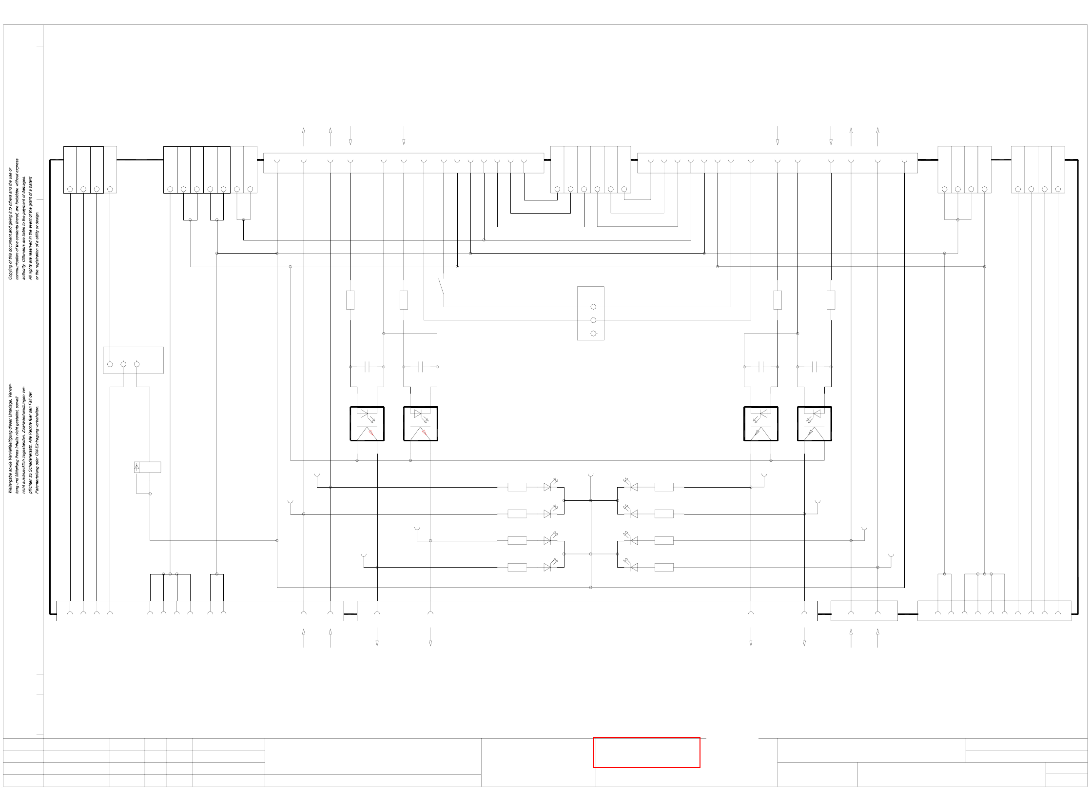
00200034-030101LD3 Optical decoupling unit
29.10.1990
Tekin
Optical decoupling
unit
1. Tu.
14.06.96
5 X6
12111091234
+ X6
+24VDC
+24VDC
+24VDC
+24VDC
Input 1
Input 2
Input 3
Input 4 Input 4
Input 3
Input 2
Input 1
+24VDC
U
U
X5
X5
P
P
M
X5
X5
X5
M X5
+30VDC unswitched
+30VDC unswitched
GND 24V
GND 24V
+24VDC
+24VDC
G X5
1234
GND 24V
GND 24V
GND 24VX6
X6
X6 -
-
-
GND 24V
GND 24V
X2 13 14
+30VDC switched
+30VDC switched
+30VDC switched
+30VDC switched
+30VDC switched
00200034-030101LD3
1.
Tu.
14.06.96
Function status
00200034
00200034-03
34
12
GND 24V
X1 9
K1
13
6
9
1 2 3
JP2
X5 8
1413
GND 24V
GND 24V
10 11 12
5
6
7
X5
X5
X5
GND 24V
Received
Permission
151413X3
65
Permission
Received
MP2
MP1
1K5 1,1W
R1
0,1uF
C1
Request
GND n-1
19 20
Request
U1
MP4
GND 24V
11
loop
K1
1
7
Fault signal
12
1K5 1,1W
R2
0,1uF
C2
Transferred
18
preceding station
To
U2
6
Transferred
2K7
R8
2K7
R7
MP3
2K7
R5
2K7
R6
Permission
Received
Transferred
Request
+24VDC
Spare
Spare
Spare
1098
+30VDC unswitched
+24VDC
123
GND 24V
X7
X7
X7
X7
X7
1
2
3
4
5
6X7
Spare
Spare
Spare
Spare
Spare
Spare
1
2
3
JP1
MP9
V2
+-
V1
+-
V3
+-
V4
+-
ye
ye
gn
gn
gn
gn
ye
ye
V8
V7
V5
V6
Spare
Spare
Spare
9810X4
+24VDC
GND 24V
+30VDC unswitched
564
2K7
R11
2K7
R12
2K7
R10
2K7
R9
Permission
Transferred
Request
Received
11
Fault signal
12
Loop
succeeding station
To
1K5 1,1W
R3
0,1uF
C3
Permission
15
7
Permission
U3
MP5
GND 24V
1K5 1,1W
R4
0,1uF
C4
Received
GND n+1
1413
8
Received
U4
MP6
Request
GND 24V
Transferred
18 19 20
7
Transferred
Request
MP7
MP8
X1 8X2 5
Tu.
14.06.96
3.
Output 1
Output 2
Output 3
Output 4Output 4
Output 3
Output 2
Output 1
6
7
8
X6
X6
X6
34
12
+-
+-
+-
+-
34
21
34
21
Name Norm
Beab.
Urspr./Ers.f./Ers.d.
Sh.
Sh.Stromlaufplan/Circuit diagramDatumAenderungZustand
Datum
Gepr.
1816151413121110987654321 17
CAD-Datei :
Mat.-Nr. :
SIEMENS
AUT 5
Product status
Document status
SMD Placement System Siplace 80S
1
1
Sh.
Sh.
S
ee page 104
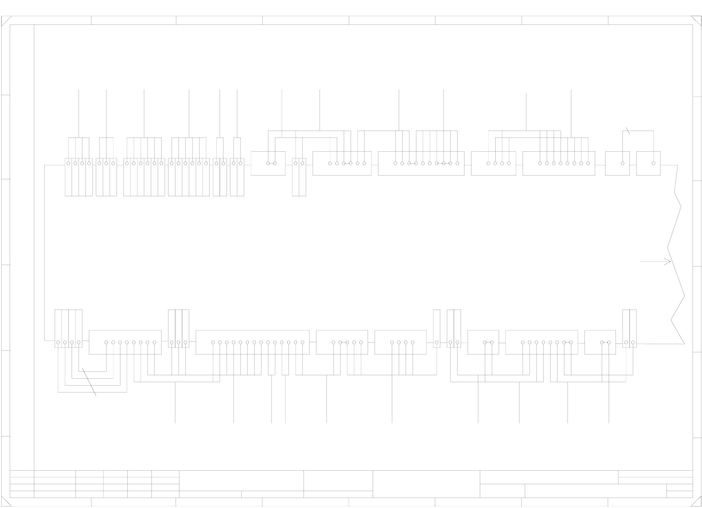
3 Circuit diagrams 86
00357878-010101LD3 Circuit diagram, terminal panel, lefthand side (Sh. 1 of 2)
Both WPC interfaces
*** are available in
Siplace 80S23 machines.
In Siplace 80S20 machines
these cables are not
available.
When wiring 80S20 machines
jumpers X211:4-5 and
X211:6-7 have to be inserted.
If a hood
switch is
installed
jumper
has to be removed!
br
rd
A1 X4ka -
A1 X2ka 3
00317579-xxW 2
bl
ye
pk
wh
A3 X2kf 4
A3 X2kf 3
A3 X3kf +
A3 X4kf -
br
rd
A1 X4ka -
A1 X2ka 4
00317579-xxW 1
bl
ye
pk
wh
A3 X2kf 6
A3 X2kf 5
A3 X3kf +
A3 X4kf -
00300912-xx
video mux.
To
00301486-xx
br
gn
wh
A2 X4kc -
A2 X2kc 6
A2 X2kc 5
indicator
main fault
To
00321509-xx
br
ye
gn
wh
A2 X4kc -
A2 X2kc 3
A2 X2kc 2
A2 X2kc 1
1.
Tuth25.05.2000
00357878-010101LD3
Terminal panel, I/O distributor
Tuth
25.05.2000
Tuth
Tuth
25.05.2000
25.05.2000
1.
1.
Document status
Product status
Function status
Siplace S25HM
Sh.
2
Sheet
1
2 X2kd A2
00322111-xx
00322112-xx
wh
3
X212
1
X211
ye
gn
br
wh
gr
pk
pk
ye
gn
br
7620 201541
X211
wh
gr
21
X210
gn/ye
wh/br
gr/pk
gn/ye
bl
rd
bk
pk
br
gn
gr
gn
gn
ye
ye
ye
br
br
wh
wh
00300182-xx
00306880-xx
00305817-xx
00305818-xx
10333921447
X212
13 2221141312
X211
A2 X3kd +
33
X210
00344225-xx
br
wh
A3 X3kf +
A3 X2kf 2
00344224-xx
br
wh
A3 X3kf +
A3 X2kf 1
33
X210
1211119101098
X211
33
X210
5 X2kd A2
+ X3kd A2
17 191816
X211
15412
X210
63225751918417161583
X211
54312241
X210
- X4kd A2
+ X3kd A2
6 X2kd A2
+ X3kd A2
3 X2kd A2
4 X2kd A2
1
F
E
D
C
B
A
Confiado como secrete industrial. Nos reservamos todos los derechos.
Comunicado como segredo empresarial. Reservados todos os direilos.
Confie a titre de secret d´entreprise. Tous droits reserves.
Proprietary date, company confidential. All rights reservd.
besondere fuer den Fall der Patenterteilung oder GM-Eintragung
pflichten zu Schadenersatz. Alle Rechte vorbehalten, ins
nicht ausdruecklich zugestanden. Zuwiderhandlungen ver-
wertung und Mitteilung ihres Inhalts nicht gestattet, soweit
Weitergabe sowie Vervielfaeltigung dieser Unterlage,Ver-
Gepr.
Bearb.
Datum
Ers.d.
Ers.f.
Urspr.NormNameDatumAenderungZustand
PLEA1 E
SIEMENS AG
21
Distance sensor
Note!
A2 X3kd +
+ X3kd A2
+ X3kd A2
sheet 2
Continued on
GND
GND
WPC (Emerg.-stop loop)
Emerg.-stop, external
WPC (Emerg.-stop loop)
GND Emerg.-stop, external
WPC (Emerg.-stop loop)
WPC (Emerg.-stop loop)
Emerg.-stop, external
GND Emerg.-stop, external
Signaling circuit Emerg.-stop button
Signaling circuit Emerg.-stop button
+5V
GND
GND
GND
+30V switched
+30V unswitched
+24V
+24V
+8V
+12V
Signaling circuit K2
Signaling circuit K1
Control circuit, protect. switch 6
Control circuit, protect. switch 6
Control circuit, protect. switch 5
Control circuit, protect. switch 5
+24V
+24V
Signaling circuit, protect. switch 5
Signaling circuit, protect. switch 6
+24V
+24V
Crash Gantry 1
Nozzle changer 2 closed
GND
Valve Nozzle changer 2
Nozzle changer 2 open
GND
+24V
GND
Valve Nozzle changer 1
Nozzle changer 1 open
Nozzle changer 1 closed
GND
GND
M54
+24V
ICOS-MC1
GND
Fault indicator lamp
Fault indicator lamp
Fault indicator lamp
Option
X211:11-12
Warning!
br
br
wh
wh
00321421-xx
machine
preceding
Hood switch
00305816-xx
ye
gn
ye
gn
00303614-xx
Input conv.
Hood switch
00305815-xx
00321417-xx
on the right
Hood switch
00321573-xx
ye
gn
wh
br
00321416-xx
on the left
Hood switch
00321573-xx
ye
gn
wh
br
vio
ye
gn
pk
gr
bk
gr/pk
rd
00321528-xx
Input conv.
operator panel
To
00321432-xx
00321528-xx
Input conv.
operator panel
To
00321433-xx
gn
ye
br
wh
00322070-xx
on the right
00322069-xx
on the left
Schnittstellen
CO tablee
br
hbr
hbr
br
00322070-xx
00322069-xx
00321529-xx
Output conv.
operator panel
To
ye
gn
pk
gr
br/gn
bk
rd
wh/ye
rd/bl
vio
gr/pk
00321434-xx
bl/bk 0.5mm²
br
00321529-xx
Output conv.
operator panel
To
00321436-xx
ye
gn
wh
+24V
+24V
Signaling circuit Protect. sw. 4
Signaling circuit Protect. sw. 3
Control circuit Protect. switch 4
Control circuit Protect. switch 4
Control circuit Protect. switch 3
Control circuit Protect. switch 3
Control circuit Protect. switch 2
Control circuit Protect. switch 2
Control circuit Protect. switch 1
Control circuit Protect. switch 1
Signaling circuit Protect. switch 2
Signaling circuit Protect. switch 1
+24V
+24V
OFF button
Control circuit 1 ON button
Control circuit 1 ON button
Control circuit 2 ON button
Control circuit 2 ON button
Control circuit ON button
Signaling circuit ON button
Signaling circuit ON button
Signaling circuit Emerg.-stop button
Signaling circuit Emerg.-stop button
Control circuit Emerg.-stop button
Control circuit Emerg.-stop button
Feeder-Crash CO table li.S1
CO table (Emerg.-stop loop)
CO table (Emerg.-stop loop)
WPC (Emerg.-stop loop)
Control circuit 1 ON button
Control circuit 1 ON button
Control circuit 2 ON button
Control circuit 2 ON button
From key switch
To key switch
Control circuit Emerg.-stop button
Control circuit Emerg.-stop button
Key switch
+24V
GND
Signaling circuit OFF button
Signaling circuit ON button
+24V
Signaling circuit Emerg.-stop button
+24V
Cover open
ON button
Emerg.-stop button
00322105-xx
righthand side
00322104-xx
lefthand side
WPC interface
To
***
1.5mm²
servo
To
X211:13-14
remove jumper
connected
switch is
If a hood
Warning!
voltages
terminal panel
To
Option
00321421-xx
machine
succeeding
Hood switch
00303617-xx
output conv.
Hood switch
Gantry 2Gantry 1
To conversion board
Nozzle changer 2Nozzle changer 1
control board
To nozzle changer
+ X3kd A2
F
E
D
C
B
A
87654321
8765432
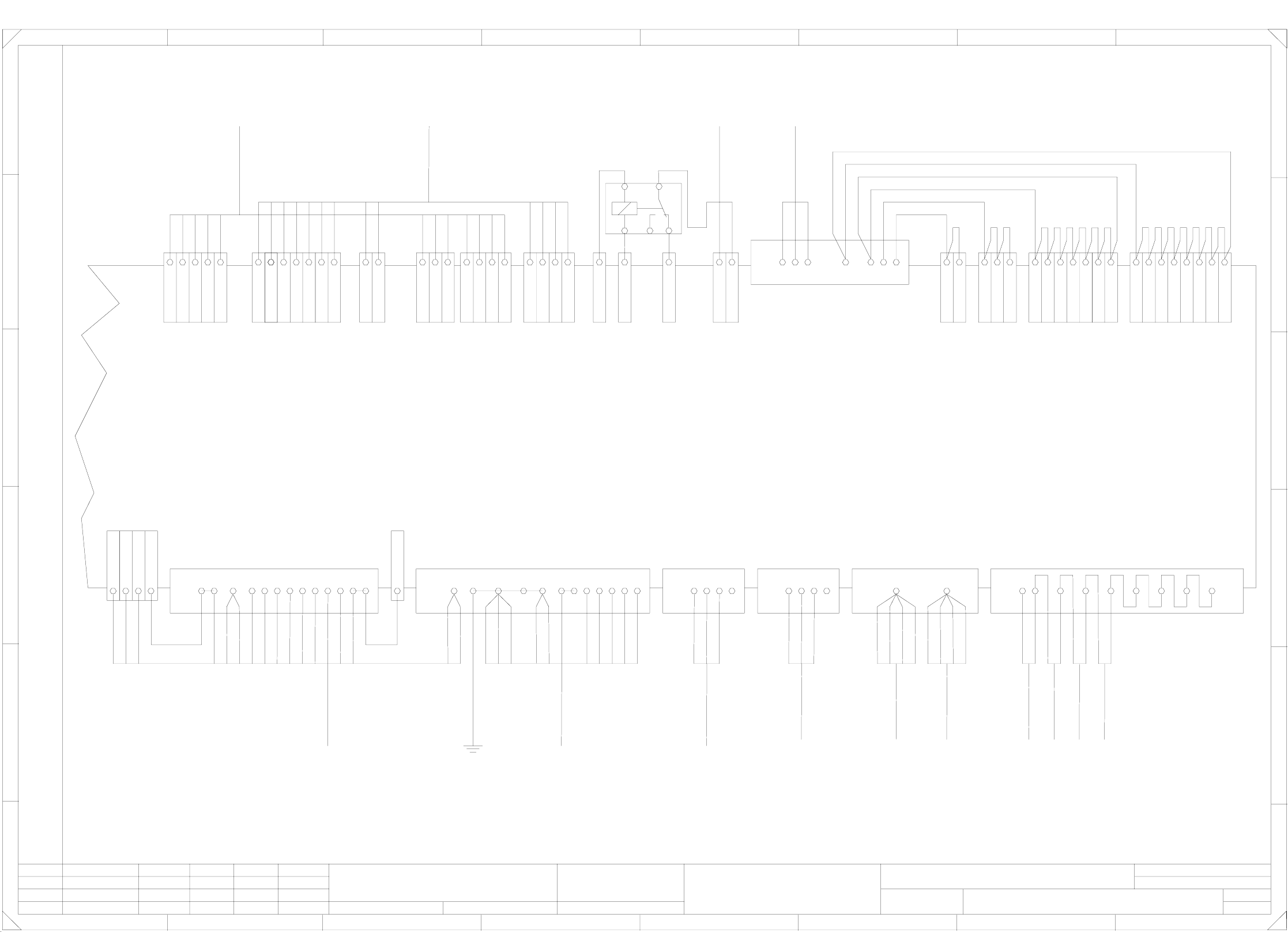
3 Circuit diagrams 87
00357878-010101LD3 Circuit diagram, terminal panel, lefthand side (Sh. 2 of 2)
4 addition feeder
crash sensors can
be connected.
Default jumper setting:
X211:25 - X211:32
A2
A1
A2 X2kd 7
A2 X2kd 3
A2 X2kd -
bk
bk
A1 X2ka 5
bk
gantry 2
conv. board
To
gantry 1
conv. board
To
gantry 2
conversion board
To
gantry 1
conversion board
To
S4
right
S3
right
S2
left
S1
left
00355468-xx
00355468-xx
00355468-xx
From CO table (Emerg.-stop loop)
To feeder crash sensor, spare 4
From feeder crash sensor, spare 3
To feeder crash sensor, spare 3
From feeder crash sensor, spare 2
To feeder crash sensor, spare 2
From feeder crash sensor, spare 1
To feeder crash sensor, spare 1
From feeder crash sensor CO table, righth. side S4
To feeder crash sensor CO table, righth. side S4
From feeder crash sensor CO table, righth. side S3
To feeder crash sensor CO table, righth. side S3
From feeder crash sensor CO table, lefth. side S2
To feeder crash sensor CO table, lefth. side S2
From feeder crash sensor CO table, lefth. side S1
wh
br
wh
br
wh
br
+24V
+5V
+5V
GND
GND
+24V
+24V
+5V
-12V
+12V
-15V
+15V
+24V
+24V
GND
GND
GND
GND
Control On K1
Control On, signal. circuit K1
External emerg.-stop circuit (WPC)
From On button to K2
To On button from K2
From On button to K1
From software relay K3
To software relay K3
Control On Sign. circuit K2
Control On Sign.circuit K2
wh
323130 8
X211
2825 2726
pk
pk
gr
ye
gn
4
00344227-xx
4
X212
ye/pk/rd
br
wh/gn/gr/bl
00344261-xx
39
10
4
X212
ye
br
wh
gr
vio
bk
bl/rd
108733
6mm² bk
K 1
Compressed air On/Off
GND
A2 X4kd -
br
gn
wh
GND
+24V
Compressed air sensor
pneumatic system
To
00322356-xx
11
12
lifting table X12
conveyor control PCB1/2
conversion board
To
Sonar sensor Output conv. 2
Sonar sensor Input conv. 2
Sonar sensor Output conv. 1
Sonar sensor Input conv. 1
Valve Ceram. substr. centering 2
Motor Width adjustment 2 wider
Motor Width adjustment 2 narrower
Motor Width adjustment 2 fast
Motor Width adjustment 1 wider
Motor Width adjustment 1 narrower
Motor Width adjustment 1 fast
Sonar sensor, cent. conv. 2
vio
wh/gn
gr/rd
A4 X6kg 8
A4 X6kg 7
A4 X6kg 6
rd/bl
A4 X6kg 5
rd/bl
bk
rd
A6 X5ki 8
A6 X5ki 7
A6 X5ki 6
gn
wh
bk
A3 X2kf 8
A1 X2kb 8
A1 X2kb 6
A1 X2kb 5
A1 X2kb 4
A1 X2kb 3
A1 X2kb 2
bl
ye
Prox.sw. Ceram. substr. 1
Prox.sw. Stopper 2 on
Sign. lifting table 1 up
Retract valve, stopper 2
GND
+5V
GND
GND
+30V switched
+30V unswitched
+24V
+24V
-15V
Sonar sensor, cent. conv. 1
Prox.sw. Pos. width adjustm. 1
Prox.sw. Stopper 1 on
Sign. lifting table 1 down
End signal width adjustm. 1
Valve Ceram. substr. centering 1
Extend valve, stopper 2
Lifting table 1 down
Lifting table 1 up
Option
Note:
br
CO tables
Feeder crash sensors
00355468-xx
gr
ye
gn
00344226-xx
ye/pk/rd
br
wh/gn/gr/bl
00344260-xx
control unit
To
00321426-xx
(frame)
Ground
ye
gr
bk
rd/bl
vio
gr/pk
power supply
To
00321113-xx
To feeder crash sensor CO table, lefth. side S1
+24V
+24V
From Emerg.-stop circuit to K2
To On button from K1
+24V
Control On, sign. circuit K1
Sign.circuit K2 Control On
Contactor K3 GND
Software release K3
Sign. circuit Software release (K3 monitoring)
X211:13-14
remove jumper
connected
switch is
If a hood
00322333-xx
video multiplexer
From
29
39
10
4
X212
161522 14
8
2
22
X211
1 X2kd A2
- X4kc A2
8 X2kc A2
7 X2kb A1
bk
br
gn 00301485-xx
12463103
X212
vio
br
rd
A6 X5ki 5
A4 X5kg 7
00326069-xx
A4 X5kg 6
A4 X5kg 5
gr
pk
A3 X2kf 7
bl
pk
lifting table X13
conveyor control PCB1/2
conversion board
To
br
A1 X2kb 1
00326068-xx
gn
wh
A1 X2ka 8
ye
gr
gr/pk
A1 X2ka 7
A1 X2ka 6
A1 X2ka 2
A1 X2ka 1
Zustand
1.
1.
1.
F
nicht ausdruecklich zugestanden. Zuwiderhandlungen ver-
wertung und Mitteilung ihres Inhalts nicht gestattet, soweit
Weitergabe sowie Vervielfaeltigung dieser Unterlage,Ver-
E
D
besondere fuer den Fall der Patenterteilung oder GM-Eintragung
pflichten zu Schadenersatz. Alle Rechte vorbehalten, ins
Confiado como secrete industrial. Nos reservamos todos los derechos.
Comunicado como segredo empresarial. Reservados todos os direilos.
Confie a titre de secret d´entreprise. Tous droits reserves.
Proprietary date, company confidential. All rights reservd.
C
B
A
12 3 4 5 6 7 8
F
E
D
C
B
A
SIEMENS AG
Gepr.
Bearb.
Datum
Norm
Product status
Aenderung
Document status
1
Function status
Tuth25.05.2000
Datum
25.05.2000 Tuth
Name
25.05.2000
Tuth
Urspr.
PLEA1 E
Tuth
2
25.05.2000
3
Ers.f.
4
Ers.d.
00357878-010101LD3
Terminal panel, I/O distributor
5
Siplace S25HM
67 8
Sheet
2
Sh.
2
wh/gn
wh/ye
43
gr/pk
pk
gn
rd/bl
46543
X212
bl/bk
0.5mm²
8 X2kd A2
0.5mm²
br/gn
gn
bl
wh
br
ye/br
bl/bk
pk/br
gr/br
wh/gr
212120191817
+30V unswitched
+30V unswitched
+30V switched
+30V switched
+30V switched
A3 X3ke M
GND
+24V
+24V
+24V
+24V
+24V
+24V
GND
GND
GND
GND
GND
GND
A1 X3ka M
A1 X3kb M
A2 X3kc M
A2 X3kd M
A3 X3kf M
A4 X5kg M
A6 X5ki M
A1 X3ka P
A1 X3kb P
A2 X3kc P
A2 X3kd P
A3 X3kf P
A4 X5kg P
A6 X5ki P
A3 X3ke P
A4 X5kg G
A6 X5ki G
A4 X5kg U
A6 X5ki U