S25 circuit.pdf - 第85页
3 Circ uit d iagrams 85 0020003 4-030 101LD3 Opti cal deco upling u nit 29.10.1 990 Tekin Optical decoupling uni t 1. Tu. 14.06.9 6 5 X6 12 11 10 9 1234 + X6 +24V DC +24V DC +24V DC +24V DC Input 1 Input 2 Input 3 Input …
3 Circuit diagrams 84
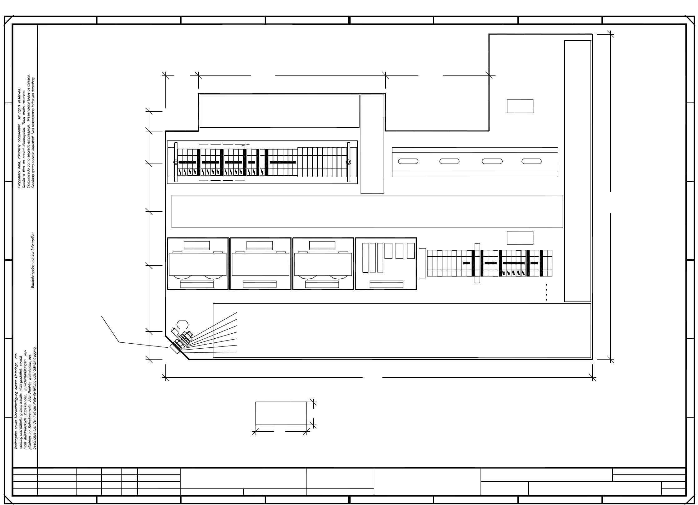
00337342-040101TD3 Terminal panel, righthand side
Document status
Product status
Function status
SMD Placement System SIPLACE S23
Sh.
1
1
Sheet
3
D
C
116mm
4
PE
D: Space for voltage label from the NAFTA label set (applies to USA only)
16
8
D
B
55mm
A5
A4
10
Cable duct 65x66 l=460mm
Please note: Break off one rib at places marked with an X
8
X
CCCC = series number
1
6
A: Identification label
END
X1rcX1rb
X2re
Please note:
Length of cable ducts: +/- 5mm
N
N
B: Inspection label
5 8
X
N
N
2
X
10
X206
L1
L1
20
AA = manufacturer/location acc. to SN 37040
BBBB = date (year/month/day) acc. to SN 01007
Cable duct 65x30
E
B
2
C
D
17
18
18
XX
315mm
0mm
9
N
5
Nut DIN 439
Kennung: Pruefer, Monat, Jahr
Assembly inscription according to guideline VA - F - 510 - 001
PE
PE
A3
X2rc
3
X
19
6
35mm
190mm
252mm
L3
L3
L3
13
14
B
X2rb
6
5
500mm
1
15
Cable duct 65x30 l=335mm
L2
PE
X
40
E
FF
Apply the following adhesive labels:
L1
L2
L2
Cable duct 65x46 l=155mm
7
345
104mm
X
X
Contact washer SN 70093
Screw
acc. to constr. specs 00343603, Sh.2
Ground connection
PE
X
X
270mm
X1rd
Nut DIN 439
Split ring DIN 7980
Washer DIN 125
Annular cable lug
A2
10
210mm
Font size 2.5, material Scothcal 3698-E (color: A1 RAL 9006)
C: Ground label
X2rd
l=120mm
A
X
PE
A
Please note: Break off one rib at places marked with an X
420mm
87
L1
4
X
XX
Cable duct 65x46 l=430mm
1
X207
A
PE
PE
PE
7
X
X
AA-BBBB-CCCC
00337342-04
SIEMENS PLEA 1
01
01
04
Deu
Deu
Tu.
X
N
L2
L3
X206
6
4
C
PE
2
PL EA1 E5
00337342-040101TD3
Terminal panel, righthand side
#
Tuth
01.09.99
19.02.99
19.02.99
01.09.99
=
Datum
Gepr.
Norm
Bearb.
Urspr. Ers. f. Ers. d.NameDatumAenderungZustand
SIEMENS AG
+
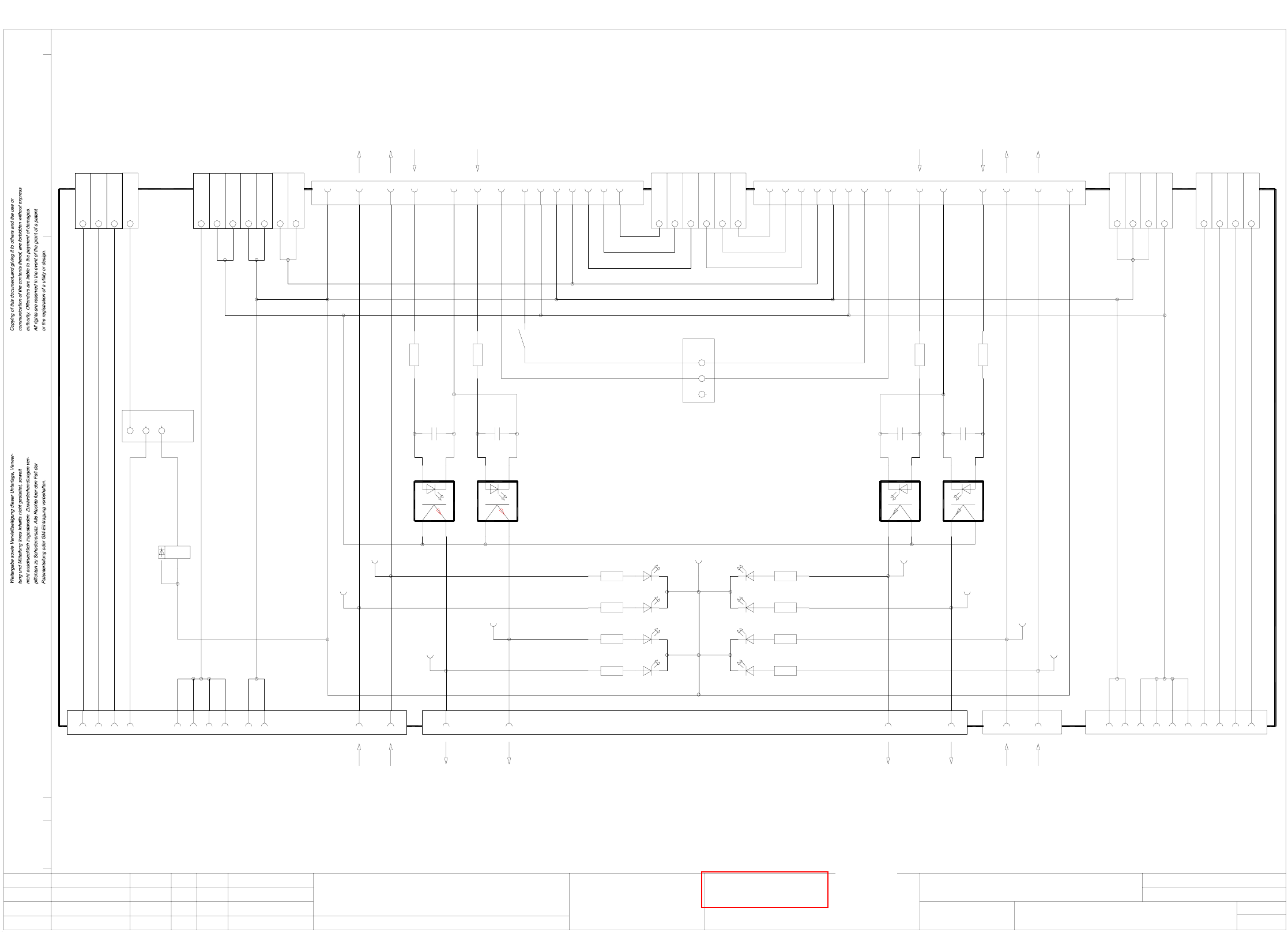
3 Circuit diagrams 85
00200034-030101LD3 Optical decoupling unit
29.10.1990
Tekin
Optical decoupling
unit
1. Tu.
14.06.96
5 X6
12111091234
+ X6
+24VDC
+24VDC
+24VDC
+24VDC
Input 1
Input 2
Input 3
Input 4 Input 4
Input 3
Input 2
Input 1
+24VDC
U
U
X5
X5
P
P
M
X5
X5
X5
M X5
+30VDC unswitched
+30VDC unswitched
GND 24V
GND 24V
+24VDC
+24VDC
G X5
1234
GND 24V
GND 24V
GND 24VX6
X6
X6 -
-
-
GND 24V
GND 24V
X2 13 14
+30VDC switched
+30VDC switched
+30VDC switched
+30VDC switched
+30VDC switched
00200034-030101LD3
1.
Tu.
14.06.96
Function status
00200034
00200034-03
34
12
GND 24V
X1 9
K1
13
6
9
1 2 3
JP2
X5 8
1413
GND 24V
GND 24V
10 11 12
5
6
7
X5
X5
X5
GND 24V
Received
Permission
151413X3
65
Permission
Received
MP2
MP1
1K5 1,1W
R1
0,1uF
C1
Request
GND n-1
19 20
Request
U1
MP4
GND 24V
11
loop
K1
1
7
Fault signal
12
1K5 1,1W
R2
0,1uF
C2
Transferred
18
preceding station
To
U2
6
Transferred
2K7
R8
2K7
R7
MP3
2K7
R5
2K7
R6
Permission
Received
Transferred
Request
+24VDC
Spare
Spare
Spare
1098
+30VDC unswitched
+24VDC
123
GND 24V
X7
X7
X7
X7
X7
1
2
3
4
5
6X7
Spare
Spare
Spare
Spare
Spare
Spare
1
2
3
JP1
MP9
V2
+-
V1
+-
V3
+-
V4
+-
ye
ye
gn
gn
gn
gn
ye
ye
V8
V7
V5
V6
Spare
Spare
Spare
9810X4
+24VDC
GND 24V
+30VDC unswitched
564
2K7
R11
2K7
R12
2K7
R10
2K7
R9
Permission
Transferred
Request
Received
11
Fault signal
12
Loop
succeeding station
To
1K5 1,1W
R3
0,1uF
C3
Permission
15
7
Permission
U3
MP5
GND 24V
1K5 1,1W
R4
0,1uF
C4
Received
GND n+1
1413
8
Received
U4
MP6
Request
GND 24V
Transferred
18 19 20
7
Transferred
Request
MP7
MP8
X1 8X2 5
Tu.
14.06.96
3.
Output 1
Output 2
Output 3
Output 4Output 4
Output 3
Output 2
Output 1
6
7
8
X6
X6
X6
34
12
+-
+-
+-
+-
34
21
34
21
Name Norm
Beab.
Urspr./Ers.f./Ers.d.
Sh.
Sh.Stromlaufplan/Circuit diagramDatumAenderungZustand
Datum
Gepr.
1816151413121110987654321 17
CAD-Datei :
Mat.-Nr. :
SIEMENS
AUT 5
Product status
Document status
SMD Placement System Siplace 80S
1
1
Sh.
Sh.
S
ee page 104
3 Circuit diagrams 86
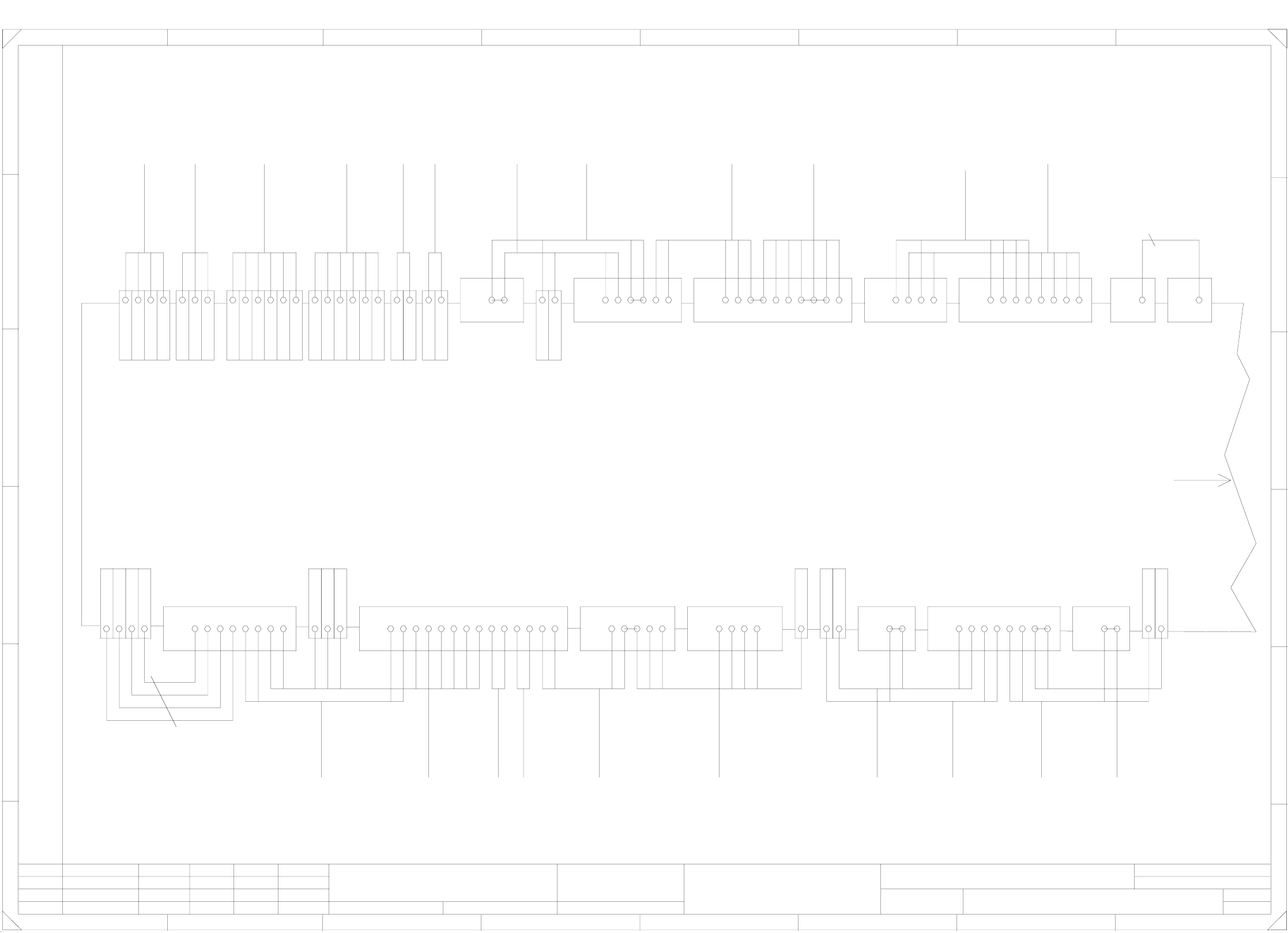
00357878-010101LD3 Circuit diagram, terminal panel, lefthand side (Sh. 1 of 2)
Both WPC interfaces
*** are available in
Siplace 80S23 machines.
In Siplace 80S20 machines
these cables are not
available.
When wiring 80S20 machines
jumpers X211:4-5 and
X211:6-7 have to be inserted.
If a hood
switch is
installed
jumper
has to be removed!
br
rd
A1 X4ka -
A1 X2ka 3
00317579-xxW 2
bl
ye
pk
wh
A3 X2kf 4
A3 X2kf 3
A3 X3kf +
A3 X4kf -
br
rd
A1 X4ka -
A1 X2ka 4
00317579-xxW 1
bl
ye
pk
wh
A3 X2kf 6
A3 X2kf 5
A3 X3kf +
A3 X4kf -
00300912-xx
video mux.
To
00301486-xx
br
gn
wh
A2 X4kc -
A2 X2kc 6
A2 X2kc 5
indicator
main fault
To
00321509-xx
br
ye
gn
wh
A2 X4kc -
A2 X2kc 3
A2 X2kc 2
A2 X2kc 1
1.
Tuth25.05.2000
00357878-010101LD3
Terminal panel, I/O distributor
Tuth
25.05.2000
Tuth
Tuth
25.05.2000
25.05.2000
1.
1.
Document status
Product status
Function status
Siplace S25HM
Sh.
2
Sheet
1
2 X2kd A2
00322111-xx
00322112-xx
wh
3
X212
1
X211
ye
gn
br
wh
gr
pk
pk
ye
gn
br
7620 201541
X211
wh
gr
21
X210
gn/ye
wh/br
gr/pk
gn/ye
bl
rd
bk
pk
br
gn
gr
gn
gn
ye
ye
ye
br
br
wh
wh
00300182-xx
00306880-xx
00305817-xx
00305818-xx
10333921447
X212
13 2221141312
X211
A2 X3kd +
33
X210
00344225-xx
br
wh
A3 X3kf +
A3 X2kf 2
00344224-xx
br
wh
A3 X3kf +
A3 X2kf 1
33
X210
1211119101098
X211
33
X210
5 X2kd A2
+ X3kd A2
17 191816
X211
15412
X210
63225751918417161583
X211
54312241
X210
- X4kd A2
+ X3kd A2
6 X2kd A2
+ X3kd A2
3 X2kd A2
4 X2kd A2
1
F
E
D
C
B
A
Confiado como secrete industrial. Nos reservamos todos los derechos.
Comunicado como segredo empresarial. Reservados todos os direilos.
Confie a titre de secret d´entreprise. Tous droits reserves.
Proprietary date, company confidential. All rights reservd.
besondere fuer den Fall der Patenterteilung oder GM-Eintragung
pflichten zu Schadenersatz. Alle Rechte vorbehalten, ins
nicht ausdruecklich zugestanden. Zuwiderhandlungen ver-
wertung und Mitteilung ihres Inhalts nicht gestattet, soweit
Weitergabe sowie Vervielfaeltigung dieser Unterlage,Ver-
Gepr.
Bearb.
Datum
Ers.d.
Ers.f.
Urspr.NormNameDatumAenderungZustand
PLEA1 E
SIEMENS AG
21
Distance sensor
Note!
A2 X3kd +
+ X3kd A2
+ X3kd A2
sheet 2
Continued on
GND
GND
WPC (Emerg.-stop loop)
Emerg.-stop, external
WPC (Emerg.-stop loop)
GND Emerg.-stop, external
WPC (Emerg.-stop loop)
WPC (Emerg.-stop loop)
Emerg.-stop, external
GND Emerg.-stop, external
Signaling circuit Emerg.-stop button
Signaling circuit Emerg.-stop button
+5V
GND
GND
GND
+30V switched
+30V unswitched
+24V
+24V
+8V
+12V
Signaling circuit K2
Signaling circuit K1
Control circuit, protect. switch 6
Control circuit, protect. switch 6
Control circuit, protect. switch 5
Control circuit, protect. switch 5
+24V
+24V
Signaling circuit, protect. switch 5
Signaling circuit, protect. switch 6
+24V
+24V
Crash Gantry 1
Nozzle changer 2 closed
GND
Valve Nozzle changer 2
Nozzle changer 2 open
GND
+24V
GND
Valve Nozzle changer 1
Nozzle changer 1 open
Nozzle changer 1 closed
GND
GND
M54
+24V
ICOS-MC1
GND
Fault indicator lamp
Fault indicator lamp
Fault indicator lamp
Option
X211:11-12
Warning!
br
br
wh
wh
00321421-xx
machine
preceding
Hood switch
00305816-xx
ye
gn
ye
gn
00303614-xx
Input conv.
Hood switch
00305815-xx
00321417-xx
on the right
Hood switch
00321573-xx
ye
gn
wh
br
00321416-xx
on the left
Hood switch
00321573-xx
ye
gn
wh
br
vio
ye
gn
pk
gr
bk
gr/pk
rd
00321528-xx
Input conv.
operator panel
To
00321432-xx
00321528-xx
Input conv.
operator panel
To
00321433-xx
gn
ye
br
wh
00322070-xx
on the right
00322069-xx
on the left
Schnittstellen
CO tablee
br
hbr
hbr
br
00322070-xx
00322069-xx
00321529-xx
Output conv.
operator panel
To
ye
gn
pk
gr
br/gn
bk
rd
wh/ye
rd/bl
vio
gr/pk
00321434-xx
bl/bk 0.5mm²
br
00321529-xx
Output conv.
operator panel
To
00321436-xx
ye
gn
wh
+24V
+24V
Signaling circuit Protect. sw. 4
Signaling circuit Protect. sw. 3
Control circuit Protect. switch 4
Control circuit Protect. switch 4
Control circuit Protect. switch 3
Control circuit Protect. switch 3
Control circuit Protect. switch 2
Control circuit Protect. switch 2
Control circuit Protect. switch 1
Control circuit Protect. switch 1
Signaling circuit Protect. switch 2
Signaling circuit Protect. switch 1
+24V
+24V
OFF button
Control circuit 1 ON button
Control circuit 1 ON button
Control circuit 2 ON button
Control circuit 2 ON button
Control circuit ON button
Signaling circuit ON button
Signaling circuit ON button
Signaling circuit Emerg.-stop button
Signaling circuit Emerg.-stop button
Control circuit Emerg.-stop button
Control circuit Emerg.-stop button
Feeder-Crash CO table li.S1
CO table (Emerg.-stop loop)
CO table (Emerg.-stop loop)
WPC (Emerg.-stop loop)
Control circuit 1 ON button
Control circuit 1 ON button
Control circuit 2 ON button
Control circuit 2 ON button
From key switch
To key switch
Control circuit Emerg.-stop button
Control circuit Emerg.-stop button
Key switch
+24V
GND
Signaling circuit OFF button
Signaling circuit ON button
+24V
Signaling circuit Emerg.-stop button
+24V
Cover open
ON button
Emerg.-stop button
00322105-xx
righthand side
00322104-xx
lefthand side
WPC interface
To
***
1.5mm²
servo
To
X211:13-14
remove jumper
connected
switch is
If a hood
Warning!
voltages
terminal panel
To
Option
00321421-xx
machine
succeeding
Hood switch
00303617-xx
output conv.
Hood switch
Gantry 2Gantry 1
To conversion board
Nozzle changer 2Nozzle changer 1
control board
To nozzle changer
+ X3kd A2
F
E
D
C
B
A
87654321
8765432