S25 circuit.pdf - 第50页
3 Circ uit d iagrams 50 001 18250-0 10101LD 2 Z-diagram, PCB conveyor 1 (Sh. 6 of 7) X3 X2 00331297-xx X3 X2 Motor X6 M 00326070-xx X3 Fan X4 00327615-xx 3 X22 8 X14 X2 Stroke/w idt h 1 X5 (conveyor 1) Light barrier, inp…
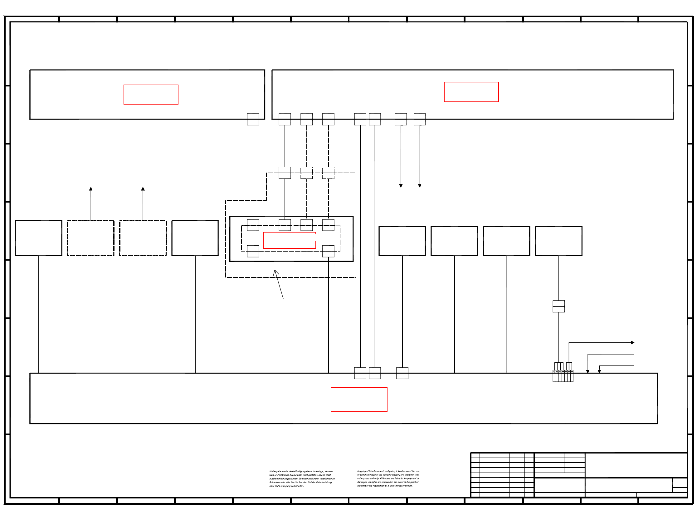
3 Circuit diagrams 49
00118250-010101LD2 Z-diagram, machine wiring 2 (Sh. 5 of 7)
1
10
X4sg
00329284-xx
X4`
X4`
X2sg
00329285-xx
89
G
H
2 7
Option
Lamp main fault indic. on the right
PCB handling
Lamp 'Ready status'
GND
00318689-xx
Icos MC1
00344239-xx
X2kc 1
br
ye
(hood switch
Protection
X2kc -
X2kc 6
X2kc 5
1
00344236-xx*)
*) Applies to option
54
GND
A
43
X4sg
X43
To preceding
station
00321580-xx
00314416-xx
Lamp main fault indic. on the left
C
11
H
A
1
X2sg
br
Main switch from
preceding station
Main switch from
00321580-xx
00321574-xx
00314417-xx
7
E
7
00326068-xx
X3`
X3`
7
G
H
Hood switch
X3sg
Servo unit
C
Voltage/signal
12
2
X14
11
X43
Part of
the options
parts list
station
M44
910
Control
00301486-xx
6
6
Conversion board
wh
D
5 10
PCB conveyor
H
F
E
X2sf
X5sg
X5sg X4sg
1
00321579-xx
(hood switch
Protection
F
12
00344238-xx
lefthand side)
C
12
A
00321421-xx
00321579-xx
Option
To succeeding
station
8
56
98
8
succeeding station
00325581-xx
X2sg
indicator
X3sg
PL EA1 E
SIEMENS AG
Zust. Aenderung Datum Name (Urspr.)
Tu.18.09.00Product status01
01 Document status 18.09.00 Tu.
01 Function status Tu.18.09.00
(Ers. f.:) (Ers. d.:)
00118250-010101LD2
7
Sh.
5
Sheet
18.09.00
Norm
Gepr.
Datum
Bearb.
SIPLACE 80S25HM1Tuth
Z-diagram, machine wiring 2
Name
00321573-xx
to preceding
00300371-xx
To user interface
x2k1
x1k1
X5`
X14
00344232-xx00329283-xx
00326070-xx
X5`
00344238-xx*)
6 11
00344265-xx
to succeeding
00343723-xx
D
Terminal panel, lefthand side
B
X34a
input conveyor
X3
33
00344236-xx
X5
5
X2kc -
B
00321421-xx
x1k1
x2k1
00356211-xx
Main fault
Control unit
9
00348262-xx
X13
12
X4sg
11
X4
X4
Hood switch
Pneumatic system
Voltage/signal
10
E
G
C
F
X2kc 3
X2kc 2
wh
X34a
X2sf
00303617-xx
00326069-xx
station
Hood switch
output conveyor
X1
00322356-xx
00303614-xx
00305815-xx
Hood switch
Lamp
X1
X12
X13
dual conveyor only
2
00321575-xx
F
X12
X3
4
D
righthand side)
Compressed air sensor
E
00300912-xx
Conversion board
PCB handling
Conversion board
2
X5
gn
gn
00344237-xx
00321509-xx
X2sg
D
B
43
B
G
A
S
ee page 72
S
ee page 65
S
ee page 115
S
ee page 86
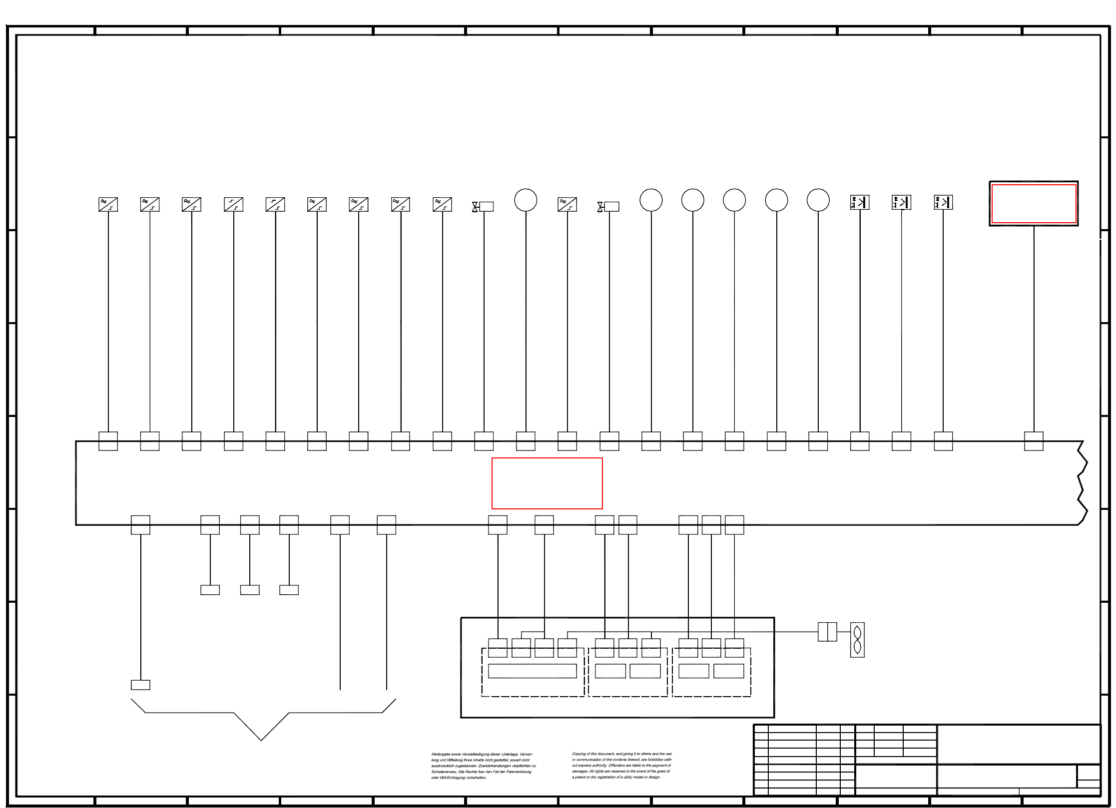
3 Circuit diagrams 50
00118250-010101LD2 Z-diagram, PCB conveyor 1 (Sh. 6 of 7)
X3X2
00331297-xx
X3X2
Motor
X6
M
00326070-xx
X3
Fan
X4
00327615-xx
3
X22
8
X14
X2
Stroke/width 1
X5
(conveyor 1)
Light barrier, input conveyor
X52
X4
00330945-xx
X1
Light barrier, center conveyor
X32
Limit switch
H
9
X5d
X44 X48
C
00326021-xx
00326028-xx
ceramic substrate centering
Proximity switch
00326026-xx
Valve
X40
X40
4
F
(conveyor 1)
D
lifting table, top
M
output conveyor
(conveyor 1)
Proximity switch
lifting table width
X36
(conveyor 1)
center conveyor
(conveyor 1)
center conveyor
00329284-xx
X34
Motor
M
X4
X7
MM
Step motor control
A
11
B
X1
(conveyor 1)
(conveyor 1)
ceramic substrate centering
X18 X20
X44
X16
X42
X50 X56
X30
1
00326064-xx
X52
2
(conveyor 1)
79
C
step motor 'width narrower'
00326030-xx
X11
5
D
00326020-xx
11 12
A
H
Proximity switch
1
X30 X32
(conveyor 1)
lifting table, bottom
X4'
Proximity switch
6
X24
X24
00326017-xx
00326033-xx
00326034-xx
00330944-xx
5
(conveyor 1)
stopper
00329285-xx
X1
X5
00329283-xx
X4
X3'
X56
X5d
00326063-xx
(conveyor 1)
Proximity switch
Limit switch
X2
X2
F
H
X13
7
X9
X13
X48 X54X46X26 X28
X38
00326024-xx
00326061-xx
7
3
G
H
G
X10
X10
00326065-xx
width adjustment
X11
00326062-xx
10
X14
X3
X16
1212
G
X18 X20
X5
X5'
4
00326029-xx
X9
X8
00326031-xx
G
X38
68
2
X14
(conveyor 1)
X12
See
X34
00326022-xx
00326027-xx
sheet 5
D
C
adhesive wiper facility
X12
00326069-xx
00326068-xx
00325581-xx
X8
00326067-xx
X5
X5
Valve
M
Motor
(conveyor 1)
X46
00326019-xx
00326018-xx
PCB conveyor control 1
10
11
X22
E
F
7
input conveyor
output conveyor
Bosch specialdesign
X50
PL EA1 E
SIEMENS AG
Zust. Aenderung Datum Name (Urspr.)
Tu.18.09.00Product status01
01 Document status 18.09.00 Tu.
01 Function status Tu.18.09.00
(Ers. f.:) (Ers. d.:)
00118250-010101LD2
7
Sh.
6
Sheet
18.09.00
Norm
Gepr.
Datum
Bearb.
SIPLACE 80S25HM1Tuth
Z-diagram, PCB conveyor 1
Name
input conveyor
Sonar proximity switch
(conveyor 1)
step motor 'width wider'
12
X6 X7
10
A
12
E
F
E
(conveyor 1)
stopper
8
X3
X4X3
Half bridge
X4
X28X26
X4
Motor
Motor
98
3
E
3
6
4
X1
10
lifting table
Stroke/width 2
(conveyor 1)
(conveyor 1)
(conveyor 1)
X5
X4X3
X54
X3
00330946-xx
X2
(conveyor 1)
00326032-xx
(conveyor 1)
Light barrier, output conveyor
Ceramic substrate
X42
centering
00330950-xx
92 6
D
5
B
C
1151
00326025-xx
Motor
A
4
BB
X5
Sonar proximity switch
(conveyor 1)
X36
X1
00326023-xx
X5
Sonar proximity switch
(conveyor 1)
S
ee page 29
S
ee page 33
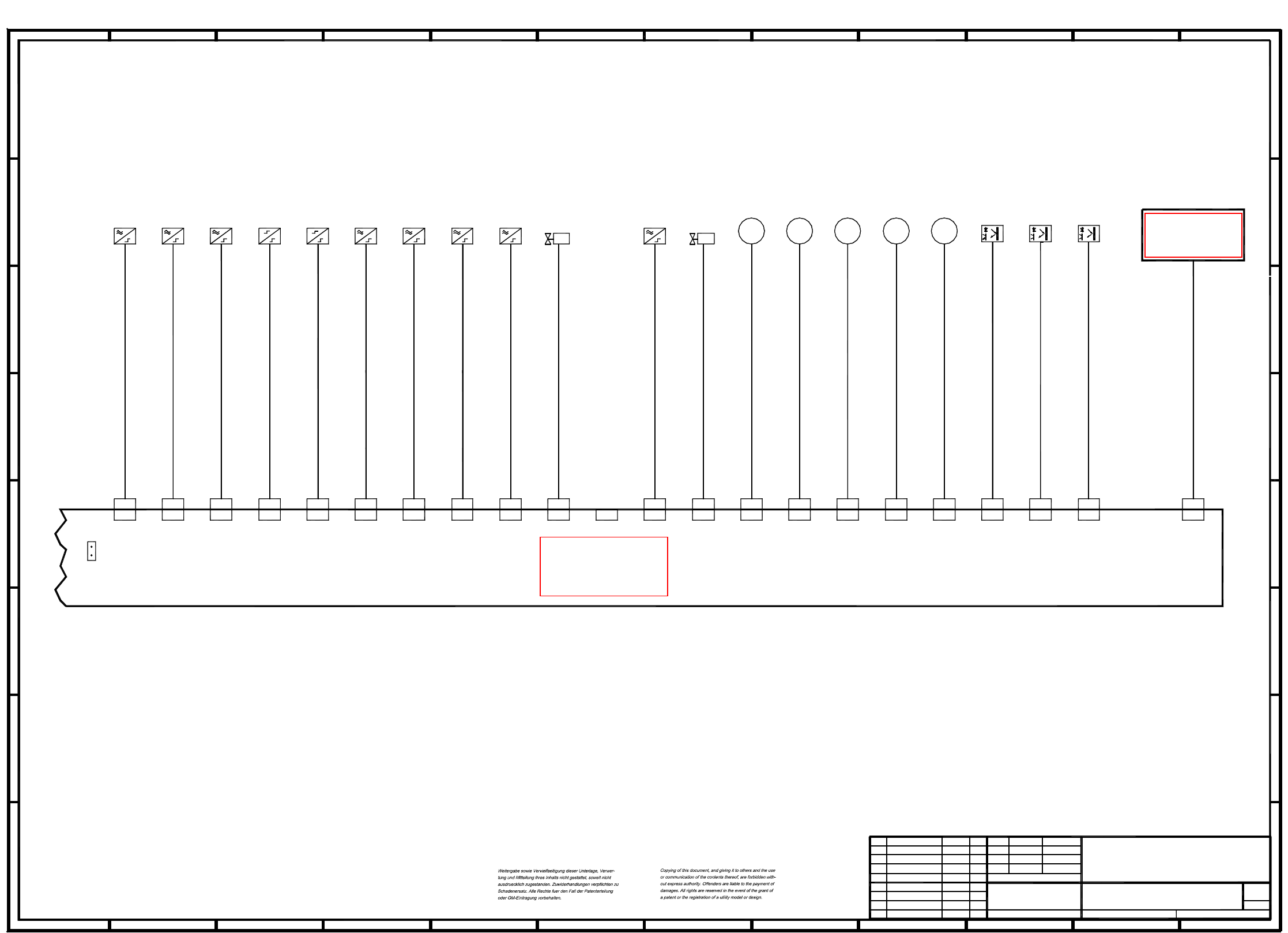
3 Circuit diagrams 51
00118250-010101LD2 Z-diagram, PCB conveyor 2 (Sh. 7 of 7)
Proximity switch
Limit switch
C
12
(Conveyor 2)
9
BB
X41X33X29
46
H
A
Sonar proximity switch
B
C
115
X27
X27 X29
00326035-xx
(Conveyor 2)
Proximity switch
PCB conveyor control 2
X55
G
H
G
CC
00326044-xx
X19 X21
X33
(Conveyor 2)
Motor
Stopper
Proximity switch
5
X49
X49X43
Output conveyor
Sonar proximity switch
9
X53
Input conveyor
Width adjustment
Output conveyor
Bosch special design
(Conveyor 2)
X31
1
X39
X39
00326043-xx
M
9
3
6
M
(Conveyor 2)
H
A
8
00330948-01
8
*X
43
X47
Ceramic substrate
centering
00330951-01
9
8
* Insert jumper X
for dual conveyors
00326036-xx
X23 X17 X15 X51 X57
X15 X51 X57
MM
lifting table width
5
X47
(Conveyor 2)
X53X19
1010
Motor
Motor
00325581-xx
D
(Conveyor 2)
X35
Motor
(Conveyor 2)
H
G
Ceramic substrate centering
3
EE
7
F
Proximity switch
Lifting table, top
X25
X25
X37
X37
00326042-xx
4
3 10
Light barrier Center conveyor
(Conveyor 2)
12
Input conveyor
Sonar proximity switch
(Conveyor 2)
(Conveyor 2)
Light barrier Output conveyor
00326045-xx
00326037-xx
G
00326051-xx
12
n. c.
2
X43
(Conveyor 2)
21 12
F
B
4
Ceramic substrate centering
Proximity switch
11
Lifting table
(Conveyor 2)
00326058-xx
D
11
11
X21
00326041-xx
Light barrier Input conveyor
(Conveyor 2)
7
X45
5
D
00326038-xx
00330947-xx
2
Valve
(Conveyor 2)
(Conveyor 2)
00326039-xx
00326049-xx
X31
M
00326056-xx
X55
00330949-01
(Conveyor 2)
F
X17X23
7
Step motor 'Width wider'
(Conveyor 2)
Lifting table, bottom
(Conveyor 2)
6
D
00326052-xx
Limit switch
00326053-xx
X35
Valve
X41
E
F
E
(Conveyor 2)
1
Motor
1 6
2
Stopper
10
A
Center conveyor
Center conveyor
8
Step motor 'Width narrower'
00326054-xx
A
(Conveyor 2)
7
PL EA1 E
SIEMENS AG
Zust. Aenderung Datum Name (Urspr.)
Tu.18.09.00Product status01
01 Document status 18.09.00 Tu.
01 Function status Tu.18.09.00
(Ers. f.:) (Ers. d.:)
00118250-010101LD2
7
Sh.
7
Sheet
18.09.00
Norm
Gepr.
Datum
Bearb.
SIPLACE 80S25HM1Tuth
Z-diagram, PCB conveyor 2
Name
S
ee page 34
S
ee page 33