S25 circuit.pdf - 第69页
3 Circ uit d iagrams 69 0035621 3-010 101FD4 S25 H M cont rol unit, basic module (Wrap con necti ons) (Sh . 3 of 3 ) S i e m e n s A G Wrap connections Drawing number: 0 0 3 5 6 2 1 3 - 0 1 0 1 0 1 F D 4 Designation: S25…
3 Circuit diagrams 68
00356213-010101FD4 S25 HM control unit, basic module (Wrap connections) (Sh. 1 of 3)
00356213-010101FD4 S25 HM control unit, basic module (Wrap connections) (Sh. 2 of 3)
Siemens AG
Wrap connections
Drawing number: 00356213-010101FD4
Designation: S25-HM control unit, base
PLEA 1 E2
Responsible : PLEA 1 E6 Ref
Wollgarten
Signature Test department Development department Page 1 of 3
Date 28.02.01
S23 Control Unit, Wrap connections incl. M54
(AMS bus with 7 slots)
Coding, axis board 1 (SP3):
Axis no. 0 (module 1)
Axis no. 1 (module 2)
Axis no. 2 (module 3)
SMP-SP3 connection:
B7
⇔
B16
⇔
B19
Coding, axis board 2 (SP4):
Axis no. 3 (module 1)
Axis no. 4 (module 2)
Axis no. 5 (module 3)
SMP-SP4 connection :
B3
⇔
B4
⇔
B9
⇔
B16
⇔
B18
⇔
B20
Coding, axis board 3 (SP5):
Axis no. 6 (module 1)
Axis no. 7 (module 2)
Axis no. 8 (module 3)
SMP-SP5 connection :
B4
⇔
B5
⇔
B7
⇔
B8
⇔
B9
⇔
B16
⇔
B21
Coding, axis board 4 (SP6):
Axis no. 9 (module 1)
Axis no. 10 (module 2)
Axis no. 11 (module 3)
SMP-SP6 connection :
B3
⇔
B6
⇔
B8
⇔
B10
⇔
B16
⇔
B18
⇔
B19
⇔
B21
AMS interrupt axis boards
Connections:
AMS-SP6 / C7
⇔
SMP-SP3 / C15
⇔
SMP-SP3 / C17
⇔
SMP-SP3 / C19
⇔
⇔
SMP-
SP4 / C15
⇔
SMP-SP4 / C17
⇔
SMP-SP4 / C19
(AMS_INT2)
AMS-SP6 / A8
⇔
SMP-SP5 / C15
⇔
SMP-SP5 / C17
⇔
SMP-SP5 / C19
⇔
⇔
SMP-SP6 / C15
⇔
SMP-SP6 / C17
⇔
SMP-SP6 / C19
(AMS_INT3)
Coding for I/O boards 1 - 3 (SP8 - SP10):
Connections:
I/O board 1 SMP-SP8 / C31
⇔
SMP-SP8 / C23
⇔
⇔
SMP-SP8 / C25
⇔
SMP-SP8 / C27
I/O board 2 SMP-SP9 / C31
⇔
SMP-SP9 / C23
⇔
⇔
SMP-SP9 / C25
I/O board 3 SMP-SP10 / C31
⇔
SMP-SP10 / C23
⇔
⇔
SMP-SP10 / C27
Siemens AG
Wrap connections
Drawing number: 00356213-010101FD4
Designation: S25-HM control unit, base
PLEA 1 E2
Responsible : PLEA 1 E6 Ref
Wollgarten
Signature Test department Development department Page 2 of 3
Date 28.02.01
Communications assembly coding (SP7):
Connection:
SMP-SP7 / B15
⇔
SMP SP7 / B4
Communications assembly interrupts (SP12 and SP13):
Connections:
(COM 3) SMP-SP7 / C15
⇔
SMP-SP1 / C25 (SMP_INT5)
(COM 4) SMP-SP7 / C17
⇔
SMP-SP1 / C27 (SMP_INT6)
(COM 5) SMP-SP7 / C19
⇔
AMS-SP6 / B8 (AMS_INT4)
(COM 6) SMP-SP7 / C21
⇔
AMS-SP6 / C8 (AMS_INT5)
(CAN-Bus 1) SMP-SP7 / C23
⇔
AMS-SP6 / A7 (AMS_INT0)
(HS3L 1) SMP-SP7 / C25
⇔
AMS-SP6 / A9 (AMS_INT6)
E/As (P218) SMP-SP8 / C15
⇔
SMP-SP9 / C15
⇔
SMP-SP10 / C15
⇔
⇔
AMS-SP6 / B7 (AMS_INT1)
AMS bus:
Connections:
AMS-SP6 / A3
⇔
AMS-SP6 / B2 (bus priority)
AMS-SP6 / A4
⇔
AMS-SP2 / A3
AMS-SP6 / B5
⇔
AMS-SP5 / B5
⇔
AMS-SP2 / B5
⇔
AMS-SP1 / B5 (battery)
Axis CAN bus
Connections:
64-pin connector above SMP-SP7 (COM351) / A15
⇔
⇔
SMP-SP6 / C13
⇔
SMP-SP6 / C23
⇔
SMP-SP6 / C29
⇔
⇔
SMP-SP5 / C13
⇔
SMP-SP5 / C23
⇔
SMP-SP5 / C29
⇔
⇔
SMP-SP4 / C13
⇔
SMP-SP4 / C23
⇔
SMP-SP4 / C29
⇔
⇔
SMP-SP3 / C13
⇔
SMP-SP3 / C23
⇔
SMP-SP3 / C29
⇔
⇔
64-pin connector above SMP-SP7 (COM351) / B13
64-pin connector above SMP-SP7 (COM351) / A16
⇔
⇔
SMP-SP6 / B12
⇔
SMP-SP6 / C21
⇔
SMP-SP6 / C25
⇔
⇔
SMP-SP5 / B12
⇔
SMP-SP5 / C21
⇔
SMP-SP5 / C25
⇔
⇔
SMP-SP4 / B12
⇔
SMP-SP4 / C21
⇔
SMP-SP4 / C25
⇔
⇔
SMP-SP3 / B12
⇔
SMP-SP3 / C21
⇔
SMP-SP3 / C25
⇔
⇔
64-pin connector above SMP-SP7 (COM351) / B14
Interrupt TSP210 - MC :
Connection:
SMP-SP11 / B5
⇔
SMP-SP9 / B5
3 Circuit diagrams 69
00356213-010101FD4 S25 HM control unit, basic module (Wrap connections) (Sh. 3 of 3)
Siemens AG
Wrap connections
Drawing number: 00356213-010101FD4
Designation: S25-HM control unit, base
PLEA 1 E2
Responsible : PLEA 1 E6 Ref
Wollgarten
Signature Test department Development department Page 3 of 3
Date 28.02.01
Connection between communications assemblies and ICOS:
Flat ribbon cable, 20-pin
Communications assembly for rear panel X99 Kombgr Rückwand X99 (via SP7)
ba
1
Pin 1 on b1
2
3
4
5
6
7
8
9
10
a10 is Key
11
Pins cut out
MM
ICOS1 rear panel
X10sv
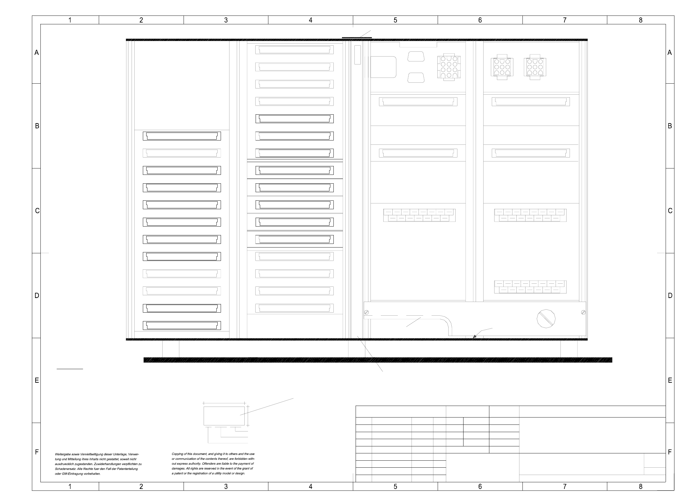
3 Circuit diagrams 70
00356213-010101TD3 S25 HM control unit (viewed from the front) (Sh. 1 of 2)
00356213 / FS
Stay bar
X1ue
Fan unit A35 (ue)
SIEMENS PL EA
AA-BBBB-CCCC
40
18
X2tsX1ts
X3ts
* Note
X8svX9sv
A33
010
X1su
X2su
X3su
X4su
X5su
X6su
X7su
X8su
X11su
X12su
SMP bus board
A32
X6rz
X7rz
AMS bus board
X22
X5rz
A36
X99
X23
X24
X25
SV backplane
A25
MVS backplane
Edge protection
X120 X121
X4rz
X3rz
X2rz
X1rz
X20
X21
X17
X19 X18
X1uz
X2uz
X3uz
X9su
X10su
X4uz
Backplane P219
A38
Battery
3.8V
00356213-010101TD3
28.06.00
28.06.00
28.06.00
28.06.00
01.
01.
02.
S25-HM control unit, basic module
(viewed from the front)
A3
1:2Massstab
28.06.2000 Tekin
Tek
Tek
Tek
(Zeichnungsnummer)
Norm
Gepr.
Bearb.
Datum
Name
NameDatumMitteilungZustand
PL EA 1 E2
SIEMENS
Stamm-Nr. FS ES US UA S F
SMD Placement System SIPLACE S25-HM
Function status
Product status
Document status
Sheet
2
Sh.
1
A: Identification label
Apply the following labels on the inside (flush with the front plate):
* Note
Font size 2.5 mm, material Scotchal 3698-E (color AI RAL 9006)
Assembly inscription according to VA-F-510-001
B: Inspection label Identification: testing engineer, month, year
Manufacturer/location according to SN 37040
Date (year/month/day) acc. to SN 01007
Series number
Function status (FS) according to the current parts list