S25 circuit.pdf - 第6页
SIPLACE S25 HM Det ailed C ircuit Diag rams Fold er 10/2003 U S Editi on 1 Symbols, S tructure of the T echnical Numberi ng System 6 1 Symbols, S tructure of the T echnical Numbering System 1.1 Leg ende/Sy mbol s 1.1.1 A…

SIPLACE S-25 HM Detailed Circuit Diagrams Folder
10/2003 US Edition
Contents 5
00325579-020101ND4 775 PCB, step motor control, power unit . . . . . . . . . . . . . . . . . . . . . . . . . . . . . . . . . 114
00325579-020101ND4 776, step motor control, control unit . . . . . . . . . . . . . . . . . . . . . . . . . . . . . . . . . . . . . 115
00325581-030101MD4 Conversion board, PCB conveyor. . . . . . . . . . . . . . . . . . . . . . . . . . . . . . . . . . . . . . . 115
00326142-050101ND3 KSP-COM351 communications assembly . . . . . . . . . . . . . . . . . . . . . . . . . . . . . . . . 116
00327250-010101MD4 I/O terminal board A1 . . . . . . . . . . . . . . . . . . . . . . . . . . . . . . . . . . . . . . . . . . . . . . . . 117
00327251-010101MD4 I/O terminal board A2 . . . . . . . . . . . . . . . . . . . . . . . . . . . . . . . . . . . . . . . . . . . . . . . . 117
00327252-010101MD4 I/O terminal board A3 . . . . . . . . . . . . . . . . . . . . . . . . . . . . . . . . . . . . . . . . . . . . . . . . 118
00327283-010101MD4 Optical decoupling unit A4 . . . . . . . . . . . . . . . . . . . . . . . . . . . . . . . . . . . . . . . . . . . . 118
00327284-010101MD4 Optical decoupling unit A6 . . . . . . . . . . . . . . . . . . . . . . . . . . . . . . . . . . . . . . . . . . . . 119
00329699-020101ND3 Control board, HS50 tape cutter (Sh. 1 of 2) . . . . . . . . . . . . . . . . . . . . . . . . . . . . . . 120
00329699-020101ND3 Control board, HS50 tape cutter (Sh. 2 of 2) . . . . . . . . . . . . . . . . . . . . . . . . . . . . . . 121
00330573-010101ND4 Interference suppression board, dp-motor . . . . . . . . . . . . . . . . . . . . . . . . . . . . . . . . 122
00330648-050101ND4 Intermed. distributor, SP6-12, digital (Sh. 1 of 2) . . . . . . . . . . . . . . . . . . . . . . . . . . . 123
00330648-050101ND4 Intermed. distributor, SP6-12, digital (Sh. 2 of 2) . . . . . . . . . . . . . . . . . . . . . . . . . . . 124
00335519-010101ND3 KSP-A362 axis (Sh. 1 of 2). . . . . . . . . . . . . . . . . . . . . . . . . . . . . . . . . . . . . . . . . . . . 125
00335519-010101ND3 KSP-A362 axis (Sh. 2 of 2). . . . . . . . . . . . . . . . . . . . . . . . . . . . . . . . . . . . . . . . . . . . 126
00335521-010101ND3 VC controller . . . . . . . . . . . . . . . . . . . . . . . . . . . . . . . . . . . . . . . . . . . . . . . . . . . . . . . 127
00335522-010101ND3 M54 machine controller, KSP-M54/COM292 (Sh. 1 of 2). . . . . . . . . . . . . . . . . . . . . 128
00335522-010101ND3 M54 machine controller, KSP-M54/COM292 (Sh. 2 of 2). . . . . . . . . . . . . . . . . . . . . 129
00335540-010101ND3 MVS rear panel board . . . . . . . . . . . . . . . . . . . . . . . . . . . . . . . . . . . . . . . . . . . . . . . .130
00336689-010101ND4 849 PCB, S25 conversion board large axis (Sh. 1 of 2) . . . . . . . . . . . . . . . . . . . . . .131
00336689-010101ND4 849 PCB, S25 conversion board large axis (Sh. 1 of 2) . . . . . . . . . . . . . . . . . . . . . .131
00336690-030201ND3 851 PCB, gantry conversion board . . . . . . . . . . . . . . . . . . . . . . . . . . . . . . . . . . . . . .132
00337333-010101ND4 Anti-crash board. . . . . . . . . . . . . . . . . . . . . . . . . . . . . . . . . . . . . . . . . . . . . . . . . . . . .133
00342582-020101ND3 S25 backplane . . . . . . . . . . . . . . . . . . . . . . . . . . . . . . . . . . . . . . . . . . . . . . . . . . . . . .134
00343908-010101ND4 856 PCB, S25 servo backplane (Sh. 1 of 2) . . . . . . . . . . . . . . . . . . . . . . . . . . . . . . .135
00343908-010101ND4 856 PCB, S25 servo backplane (Sh. 2 of 2) . . . . . . . . . . . . . . . . . . . . . . . . . . . . . . .135
00344485-010101ND4 877 PCB, 80C515C prozessor board (Sh. 1 of 2) . . . . . . . . . . . . . . . . . . . . . . . . . . .136
00344485-010101ND4 877 PCB, 80C515C prozessor board (Sh. 2 of 2) . . . . . . . . . . . . . . . . . . . . . . . . . . .136
00344486-010101ND3 878 PCB, S25 gantry head distributor (Sh. 1 of 2). . . . . . . . . . . . . . . . . . . . . . . . . . .137
00344486-010101ND3 878 PCB, S25 gantry head distributor (Sh. 2 of 2). . . . . . . . . . . . . . . . . . . . . . . . . . .138
00344488-020101ND4 873 PCB, step motor board, modular (Sh. 1 of 2) . . . . . . . . . . . . . . . . . . . . . . . . . . .139
00344488-020101ND4 873 PCB, step motor board, modular (Sh. 2 of 2) . . . . . . . . . . . . . . . . . . . . . . . . . . .139
00344489-010101ND4 874 PCB, vision board module (Sh. 1 of 2) . . . . . . . . . . . . . . . . . . . . . . . . . . . . . . . .140
00344489-010101ND4 874 PCB, vision board module (Sh. 2 of 2) . . . . . . . . . . . . . . . . . . . . . . . . . . . . . . . .140
00345015-010101ND4 854 PCB, S25 axis rear panel for X/Y/star. . . . . . . . . . . . . . . . . . . . . . . . . . . . . . . . .141
00345016-010101ND4 854 PCB, S25 axis rear panel for Z/DP . . . . . . . . . . . . . . . . . . . . . . . . . . . . . . . . . . .141
00346057-010101ND4 854 PCB, S25 axis rear panel for Z/DP, type II . . . . . . . . . . . . . . . . . . . . . . . . . . . . .142
6 Pneumatic diagrams
00341199-010302XD1 S25 pneumatic diagram . . . . . . . . . . . . . . . . . . . . . . . . . . . . . . . . . . . . . . . . . . . . . . 143
00328647-010201XD3 Tape cutter, pneumatically operated. . . . . . . . . . . . . . . . . . . . . . . . . . . . . . . . . . . . . 144
00329906-010101EX3 Pneumatic symbols. . . . . . . . . . . . . . . . . . . . . . . . . . . . . . . . . . . . . . . . . . . . . . . . . . 145
SIPLACE S25 HM Detailed Circuit Diagrams Folder
10/2003 US Edition
1 Symbols, Structure of the Technical Numbering System 6
1 Symbols, Structure of the Technical Numbering System
1.1 Legende/Symbols
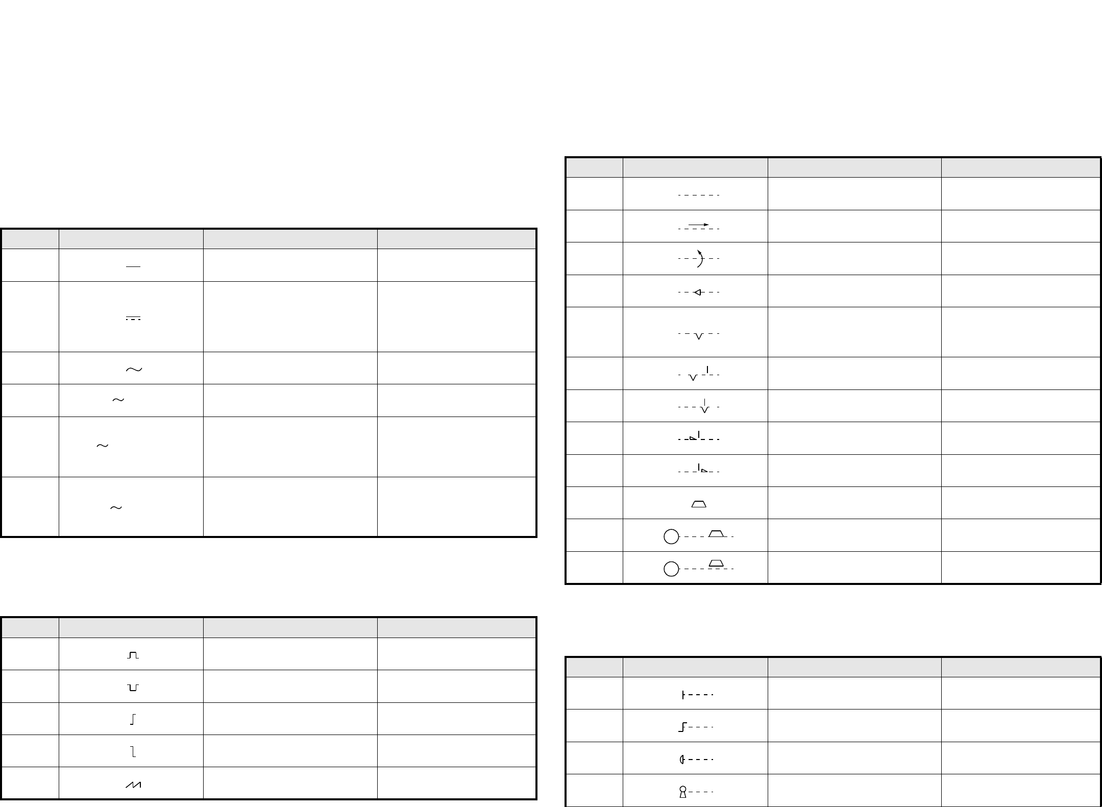
1.1.1 Arten von Strömen und Spannungen / Kind of current and voltage
1.1.2 Impulsformen / Signal waveforms
1.1.3 Mechanische Stellteile / Mechanical controls
1.1.4 Antriebsarten / Operating devices and methods
Nr. / No. Schaltzeichen / Symbol Beschreibung Description
02-02-01 Gleichstrom Direct current
02-02-03
Gleichstrom
Anmerkung:
Das Schaltzeichen 02-02-03 muß ange-
wendet werden, wenn das Schaltzei-
chen 02-02-01 zu Verwechslungen
führt.
Direct current
Note:
Symbol 02-02-03 is to be used if
symbol 02-02-01 causes confusion.
02-02-04 Wechselstrom Alternating current
02-02-05 Wechselstrom, 50 Hz Alternating current of 50 Hz
02-02-07
Dreiphasen-Vierleitersystem mit drei
Außenleitern und einem Neutralleiter,
50 Hz, 400 V (230 V zwischen jedem
Außenleiter und dem Neutralleiter).
3N darf durch 3/N ersetzt werden.
Alternating current: three-phase
with neutral, 50 Hz, 400 V (230 V
between phase and neutral).
3N may be replaced by 3 + N.
02-02-08
Dreiphasen-Fünfleitersystem mit drei
Außenleitern, einem Neutralleiter und
einem Schutzleiter, 50 Hz, direkte
Erdung eines Punktes, Neutral- und
Schutzleiter getrennt.
Alternating current, three-phase, 50
Hz: system having one point directly
earthed and separate neutral and
protective conductors throughout.
Nr. / No. Schaltzeichen / Symbol Beschreibung Description
02-10-01 Positiver Impuls Positive-going pulse
02-10-02 Negativer Impuls Negative-going pulse
02-10-04 Positive Schrittfunktion Positive-going step function
02-10-05 Negative Schrittfunktion Negative-going step function
02-10-06
Sägezahn Saw-tooth
50 Hz
3N 50 Hz 400/230 V
3/N/PE 50 Hz / TN - S
Nr. / No. Schaltzeichen / Symbol Beschreibung Description
02-12-01 Wirkverbindung, allgemein Mechanical connection (link)
02-12-02
Mechanische Verbindung mit Angabe
der Richtung von Kraft oder Bewegung
Mechanical connection with indica-
tion of direction of force or motion
02-12-03
Mechanische Verbindung mit Angabe
der Drehrichtung
Mechanical connection with indica-
tion of direction of rotation
02-12-07 Selbsttätiger Rückgang Automatic return
02-12-08
Raste
Nicht selbsttätiger Rückgang
Einrichtung zum Beibehalten einer
gegebenen Stellung
Detent
Non-automatic return
Device for maintaining a given posi-
tion
02-12-09 Raste, nicht eingerastet Detent, disengaged
02-12-10 Raste, eingerastet Detent, engaged
02-12-12 Sperre, nicht verklinkt Latching device, disengaged
02-12-13 Sperre, verklinkt Latching device, engaged
02-12-20 Bremse Brake
02-12-21 Elektromotor mit eingelegter Bremse Electric motor with brake applied
02-12-22 Elektromotor mit gelöster Bremse Electric motor with brake released
Nr. / No. Schaltzeichen / Symbol Beschreibung Description
02-13-01 Handantrieb, allgemein
Manually operated control,
general symbol
02-13-04 Betätigung durch Drehen Operated by turning
02-13-08 Notschalter
Emergency switch (mushroom-head
safety feature)
02-13-13 Betätigung durch Schlüssel Operated by key
M
M
SIPLACE S25 HM Detailed Circuit Diagrams Folder
10/2003 US Edition
1 Symbols, Structure of the Technical Numbering System 7
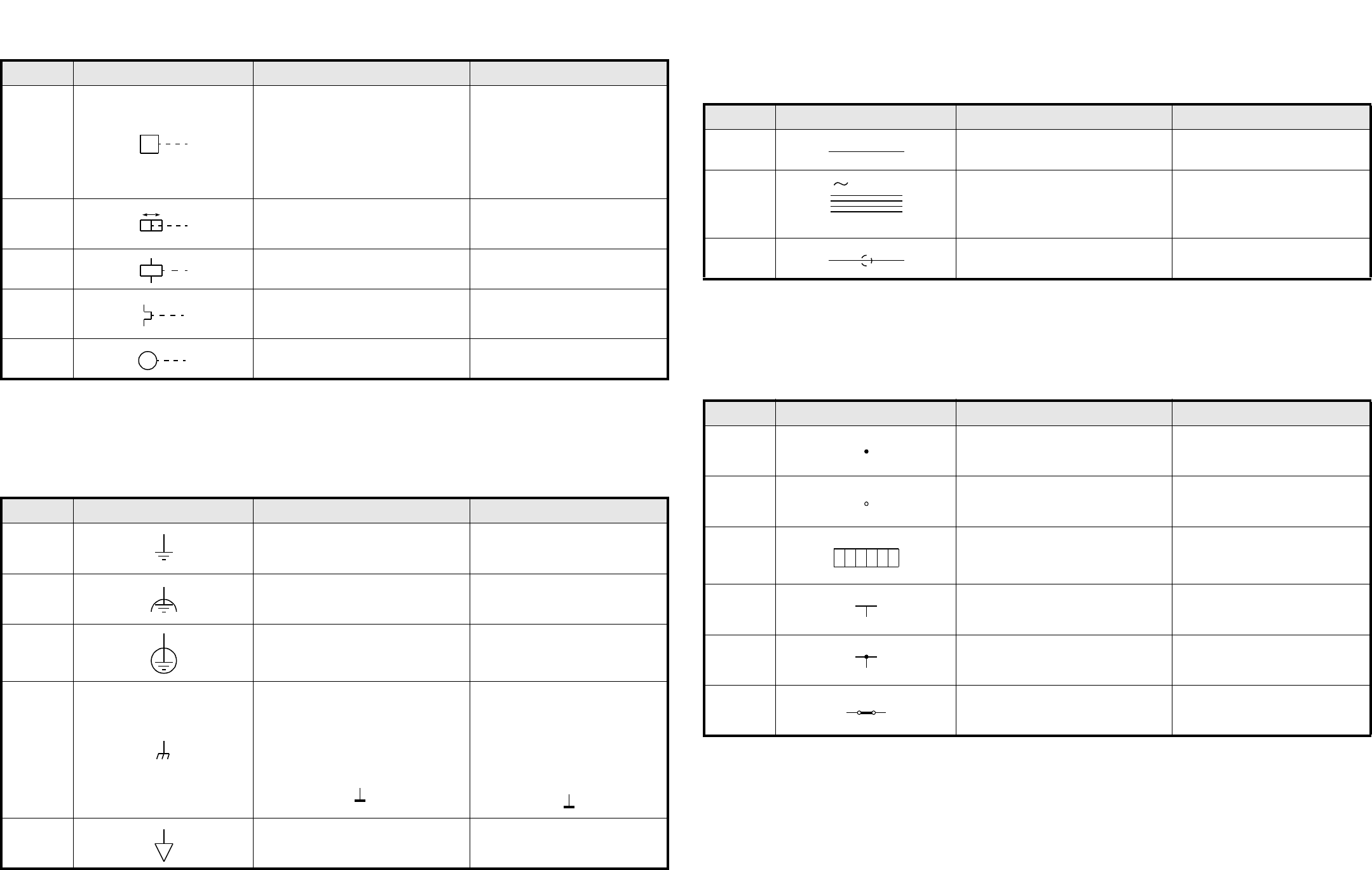
1.1.5 Erde, Masse, Äquipotential /
Earth and frame connections, equipotentiality
1.1.6 Leiter / Conductors
1.1.7 Anschlüsse und Leiterverbindungen /
Terminals and connections of conductors
Nr. / No. Schaltzeichen / Symbol Beschreibung Description
02-13-20
Kraftantrieb, allgemein
Betätigung durch gespeicherte mecha-
nische Energie
Anmerkung:
Hinweise auf die Art der gespeicherten
Energie dürfen in das Quadrat eingetra-
gen werden (z. B. Formelzeichen nach
DIN 1304).
Drive, general symbol
Operated by stored mechanical
energy
Note:
Information showing the form of
stored energy may be added in the
square.
02-13-22
Betätigung durch pneumatische oder
hydraulische Steuerung in beiden Rich-
tungen
Operated by pneumatic or hydraulic
control, double acting
02-13-23
Betätigung durch elektromagnetischen
Antrieb
Operated by electromagnetic actua-
tor
02-13-25
Betätigung durch thermischen Antrieb,
z. B. Bimetallrelais
Thermischer Überstromschutz
Operated by thermal actuator, for
example thermal relay, thermal
overcurrent protection
02-13-26 Betätigung durch Motor Operated by electric motor
Nr. / No. Schaltzeichen / Symbol Beschreibung Description
02-15-01 Erde, allgemein
Earth, general symbol
Ground, general symbol
02-15-02 Fremdspannungsarme Erde
Noiseless earth
Noiseless ground
02-15-03 Schutzerde
Protective earth
Protective ground
02-15-04
Masse
Gehäuse
Anmerkung:
Die Schraffur darf entfallen, wenn keine
Unklarheit besteht. Die Linie, die das
Gehäuse repräsentiert, muß dann brei-
ter dargestellt werden:
Frame
Chassis
Note:
The hatching may be completely or
partly omitted if there is no ambigu-
ity. If the hatching is omitted, the line
representing the frame or chassis
shall be thicker as shown below:
02-15-05 Äquipotential Equipotentiality
M
Nr. / No. Schaltzeichen / Symbol Beschreibung Description
03-01-01 Leiter Conductor
03-01-05
Dreiphasen-Vierleitersystem mit drei
Außenleitern und einem Neutralleiter,
50 Hz, 400 V, Außenleiter 120 mm
2
,
Neutralleiter 50 mm
2
Three-phase circuit, 50 Hz, 400 V,
three conductors of 120 mm
2
, with
neutral of 50 mm
2
03-01-07 Leiter, geschirmt Screened conductor
Nr. / No. Schaltzeichen / Symbol Beschreibung Description
03-02-01 Verbindung von Leitern Connection of conductors
03-02-02
Anschluß (z. B. Klemme)
Anmerkung:
Der Kreis darf ausgefüllt werden.
Termi nal
Note:
The circle may be filled in.
03-02-03
Anschlußleiste, dargestellt mit
Anschlußbezeichnungen
Terminal strip, example shown with
terminal markings
03-02-04 Abzweig von Leitern Junction of conductors
03-02-05 Abzweig von Leitern Junction of conductors
03-02-08 Leiter-Verbindungsstück Conductor joint
3N 50 Hz 400 V
3 x 120 x 1 x 50
1112 15161314