S25 circuit.pdf - 第73页
3 Circ uit d iagrams 73 0034372 3-010 201 TD3 Servo u nit (vi ewed fr om the fro nt) (Sh . 1 of 2 ) = Datum Gepr. Norm Bearb. Urspr. Ers. f . Ers. d. Name Dat um Aenderung Zustand SIEMENS AG + PL EA1 E 15.01.99 18.09.98 …
3 Circuit diagrams 72
00343723-010101LD3 S25 servo unit
F
Leh
PL EA1 E
+15V
+15V
+15V
+15V
-15V
-15V
-15V
-15V
-15V
-15V
1L-
1L-
6L+
Motor
1L+/GND
Voltage +/-15V
Anti-crash board
Tacho
Nom. values
Motor
1L+/GND
Anti-crash board
Voltage +/-15V
Nom. values
Tacho
(va)
A18
(vb)
A19
(vo)
A27 A10
A9A26
(vp)
A25 A8
(vr)
2L+/5L+ SP head
SP head3L+
3L+ SP head
Nom. values
Tacho
Motor
Voltage
Voltage
Motor
Tacho
Nom. values
Voltage
Tacho
Motor
Nom. values
Voltage
Tacho
Motor
Nom. values
Voltage
Motor
Tacho
Nom. values
A21
(vd)
A4
SP head 3L+
3L+SP head
A3 A20
(vf)
Ballast circuit
Anti-crash board
X1
X11
X4vc X3vc X2vc
X1
X1vc
Star
Servo amplifier
(gantry 1)
(gantry 1)
Star
Backplane
(gantry 1)
z axis
Servo amplifier
(gantry 1)
Servo amplifier
dp1 axis
Backplane
(gantry 1)
z axis
(gantry 1)
Backplane
dp1 axis
X4vd X3vd X2vd X2vfX3vfX4vf
gantry 1
Backplane
x axis
X1
X1vd X1vf
X1
X5va
X5va
X4va
X4va
X8va X7va X6va X1vaX2vaX3va
A11 A1
x axis
gantry 1
Dynamic brake Servo amplifier
gantry 1
x axis
Dynamic brake
gantry 2
A13
x axis
gantry 2
A2
x axis
Servo amplifier
X5vm
X5vm
X4vm
X4vm
gantry 2
x axis
Backplane
X8vm X7vm X6vm X3vm X2vm X1vm
X5vb
X5vb X4vb
X4vb
X4vn
X4vnX5vn
X5vn
gantry 1
y axis
Backplane
gantry 2
Backplane
y axis
X1vbX2vbX3vbX6vbX7vbX8vb
X1vnX2vnX3vnX6vnX7vnX8vn
A12 A6A7A14
gantry 1
y axis
Servo amplifierDynamic brake
gantry 1
y axis
gantry 2
Servo amplifier
y axis
gantry 2
Dynamic brake
y axis
X4vp X3vp X2vp
X2vrX3vrX4vr
X1vp
X1
X1vr
X1
gantry 2
z axis
Backplane Backplane
dp1 axis
gantry 2
dp1 axis
gantry 2
Servo amplifierServo amplifier
z axis
gantry 2
Backplane
Star
gantry 2
Servo amplifier
gantry 2
Star
X1vo
X1
X4vo X3vo X2vo
32
Power supply unit
(+/-15V)
OutputInput
30 2628 18202224 10121416 468
X12
=
Datum
Gepr.
Norm
Bearb.
Blatt
Urspr. Ers. f. Ers. d.NameDatumAenderungZustand
SIEMENS AG
Bl.
+
678
12345678
A
B
F
E
D
C
B
A
12345
C
D
E
Leh
Leh
01
01
01
18.09.98
18.09.98
18.09.98
18.09.98
Werner
#
Servo unit, S23
00343723-010101LD3
SMD-Placement System Siplace S23
Product status
Doc. status
Function status
A15A16
GND
150V
a2
a4
a8
a6
X13
c8
c6
c4
c2
Nom. values
A5 A22
(vc)
2L+/5L+SP head
Motor
Tacho
Voltage
Tacho
Nom. values
(vm)
A23
Voltage +/-15V
Anti-crash board
1L+/GND
Motor Motor
1L+/GND
Anti-crash board
Voltage +/-15V
Nom. values
Tacho
(vn)
A24
+15V
A17
+15V
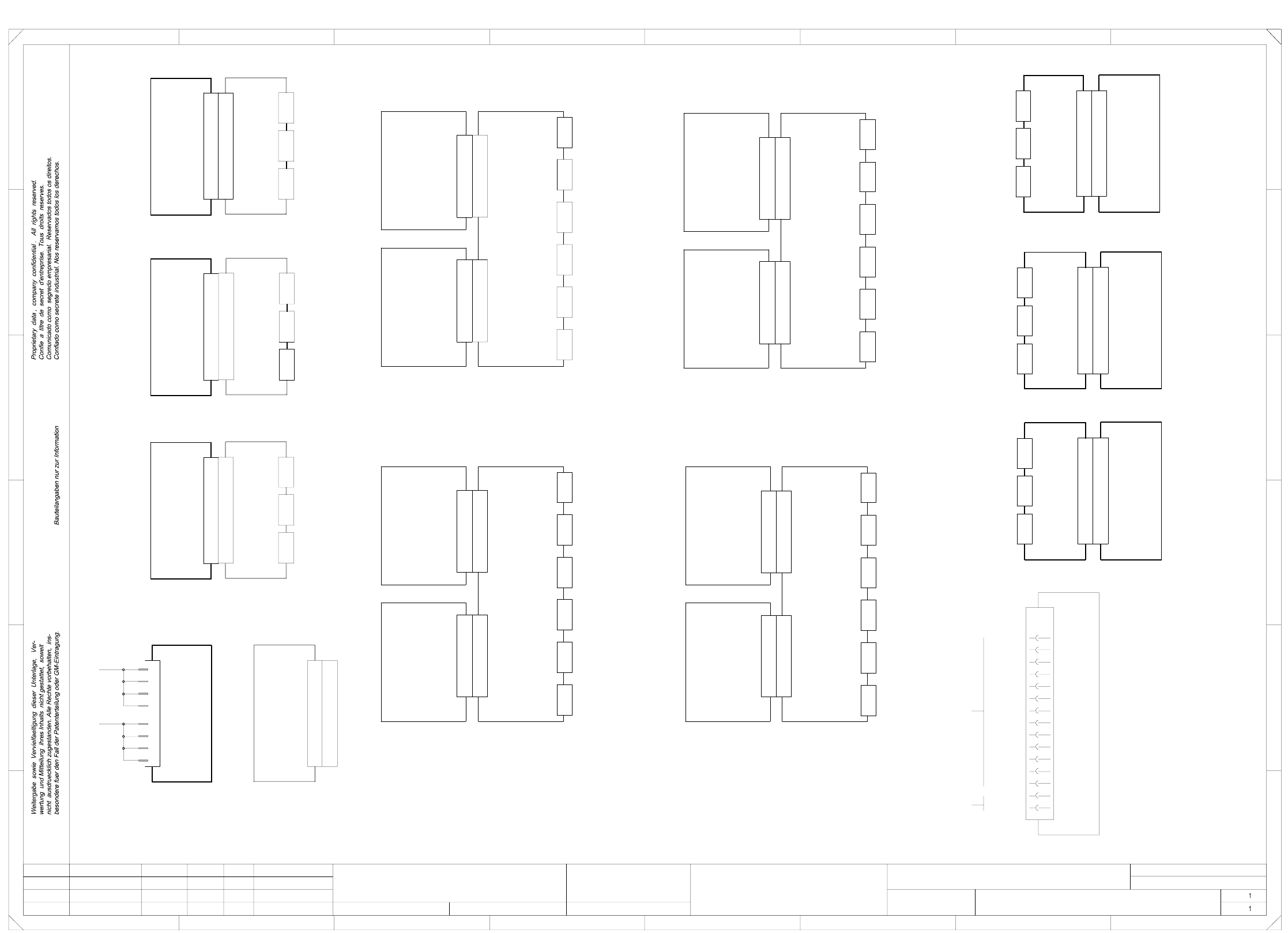
3 Circuit diagrams 73
00343723-010201TD3 Servo unit (viewed from the front) (Sh. 1 of 2)
=
Datum
Gepr.
Norm
Bearb.
Urspr. Ers. f. Ers. d.NameDatumAenderungZustand
SIEMENS AG
+
PL EA1 E
15.01.99
18.09.98
00343723-010201TD3#
Werner
15.01.99
18.09.98
Z-axis II 'A9'
Star II 'A10'
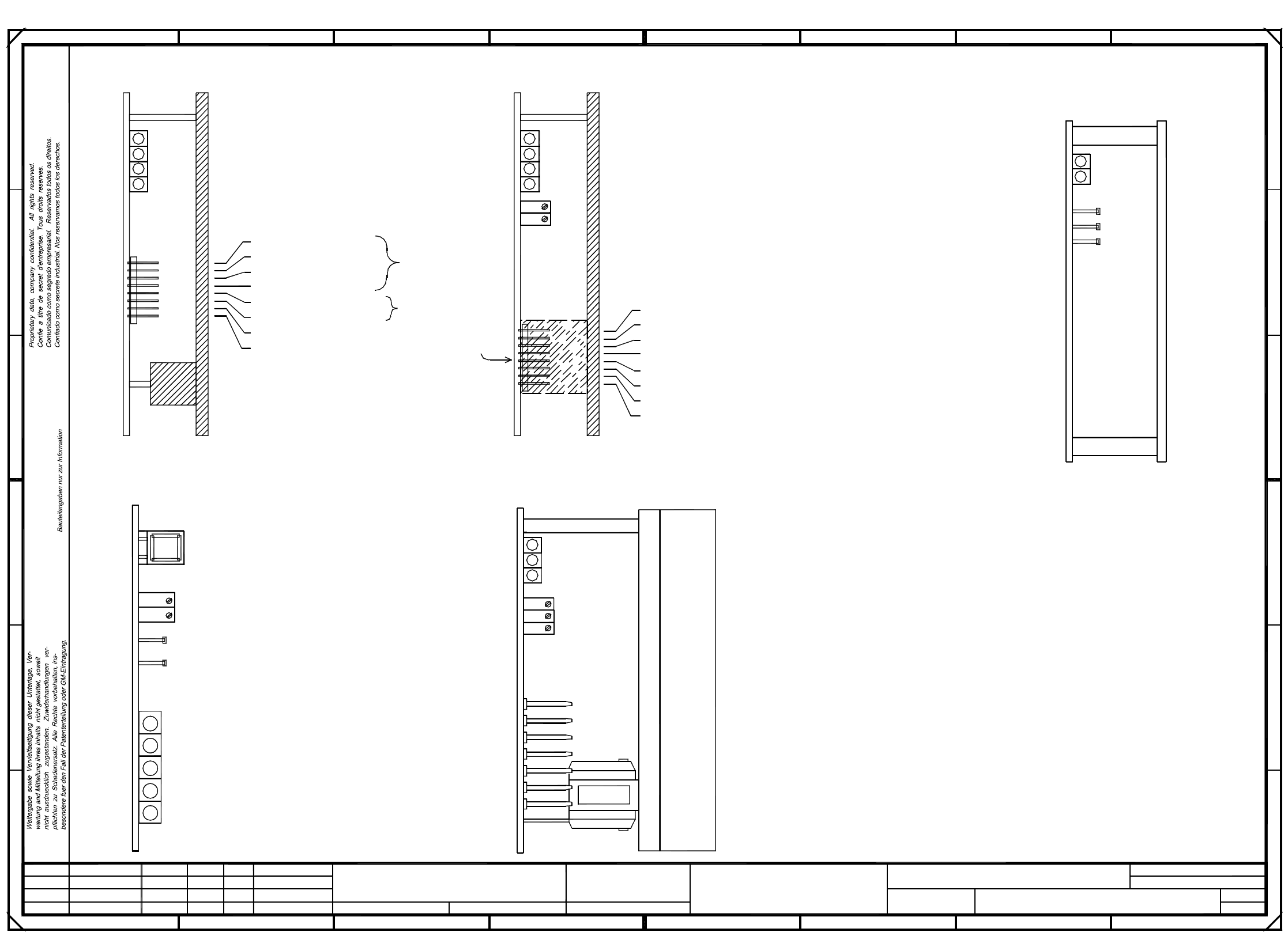
A: Identification label, module inscription acc. to VA-F-510-001
Series number
* Please note:
Manufacturer/location acc. to SN 37040
Date (year/month/day) acc. to SN 01007
1
Ballast
54
7L+
007
GND
2L+/5L+
002
2L+
Z-axis, gantry 2Star axis, gantry 2
13005
Gantry 1
Star
Gantry 1Gantry 1
Z-axisDP1-axis
Power supply unit
X-axis, gantry 2Brake, X-axis, gantry 2 Anti-crash boardX-axis, gantry 1Brake, X-axis, gantry 1
Brake, Y-axis, gantry 1
Y-axis, gantry 1
Y-axis, gantry 2Brake, Y-axis, gantry 2
Power supply unit 'A17'
DP1-axis II 'A8'
A
1 87
004
Z-axis I 'A4'
Star I 'A5'
Gantry I
Fan unit A28
Anti-crash board 'A15'
gantry II
DP1-axis I 'A3'
6L+ 5V
006005
009008
12V
1L+
* Note
001
B: Inspection label Identification: testing engineer, month, year
003
DP1-axis, gantry 2
MJE
Ballast circuit 'A16'
2
B
3
18
40
SIEMENS PLEA1
AA - BBBB - CCCC
00343723-01
24V
(flush with the front plate):
Apply the following labels on the outside
2345678
A
B
C
D
E
FF
E
D
C
01
02
01
Leh
Deu
Leh
Servo unit (viewed from the front)
MJE
13005
MJE
13005
MJE
13005
6
Document status
Product status
Function status
SMD Placement System SIPLACE S23
Sh.
2
1
Sheet
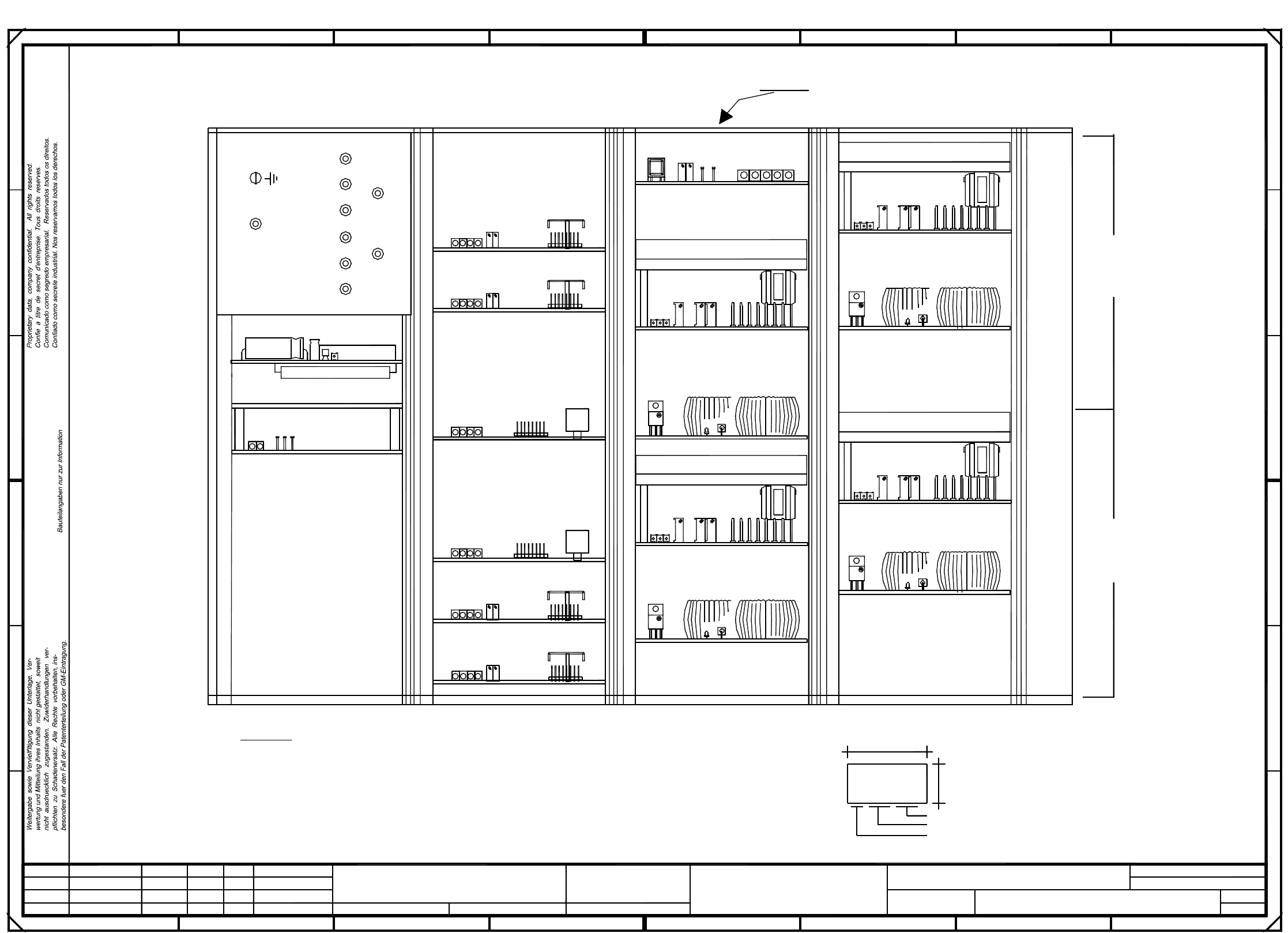
3 Circuit diagrams 74
00343723-010201TD3 Assembly overview (Sh. 2 of 2)
PL EA1 E
18.09.98
15.01.99
00343723-010201TD3
Assembly overview
#
Werner
15.01.99
10V correspond
to max. motor
Scaling:
10V correspond
Note:
TDS 120A 2,5Z
Ta Tachometer (echte Tachometerspannung)
Is Current nom. value (Ausg.Drehzahlregler)
IA Motorstellgroesse (Ausg. Stromregler)
0V Amplifier electronic, GND
Ss Sensorstop-Signal
TBS120/2,5S
12
F
Power supply unit
I r.m.s. limiting (I² x t signal)
Ready status
Fault
P gain
Tachometer
Servo board, star axis
I r.m.s. limiting (I² x t signal)
Fault
Ready status
Output stage, enable
Iact(U) Current actual value
Iact(W) Current actual value
Vnom(U) Current regulator output
3
OV Amplifier electronic, GND
Ns Nominal speed
Y-axis, gantry II
Distance sensor
Anti-crash board
0V Reference potential
Spare
Vnom(W) Current regulator output
Is(U) Current nom. value
Is(W) Current nom. value
to max. current
of device
Scaling:
78
1234
Iv Current monitor, phase V
Is Current nom. value (Ausg.Drehzahlregler)
P gain
Servo board, Z-axis
Servo board, DP1-axis
Output stage, enable
Ready status
Fault
TDS120/1D
Zero point, distance sensor
Reset button
D
C
A
B
678
A
B
C
D
E
X-axis, gantry II
Iu Current monitor, phase U
E
+15V
Heat sink installed for Z-axis only
Offset
-15V
654
=
Datum
Gepr.
Norm
Bearb.
Urspr. Ers. f. Ers. d.NameDatumAenderungZustand
SIEMENS AG
+
5
+15V
GND
-15V
and Y-axis TBF 120/12 TS
AGND
Analog voltage, distance sensor
Ii Current actual value
Ns Nominal speed
Ie Sollwert Krafteingang
I r.m.s. limiting (I² x t signal)
Tachometer
18.09.98
01
02
01
Leh
Deu
Leh
Ni Actual speed
F
Amplification, distance sensor
Y-axis, gantry I
Servo board, X-axis TBF 120/7 TS
FD Fault diagnosis
X-axis, gantry I
Document status
Product status
Function status
SMD Placement System SIPLACE S23
Sh.
2
2
Sheet
voltage