7OM-1625-004_w.pdf - 第104页
7OM-1603 Chapter 3 : 1. Maintenance Menu 3-5 1.2.2 Detachment Procedure of Multi-Layer T ray Procedure (1) Select the tray unit to be ch anged in the "Unit select" section box in the "Unit Chg." menu.…

7OM-1603
3-4
Chapter 3 : 1. Maintenance Menu
1.2.1 Attachment Procedure of Multi-Layer Tray
Procedure
(1) Select the tray unit to be changed in the "Unit select" section box in the "Unit
Chg." menu.
(2) Press the [Tray Attach Oder] button in the "Change Order Guidance" section.
(3) Connect the traverse cart connecting bundled connector to the main machine
and position it on the main machine positioning section.
(4)
Move the elevator unit to the attachment position and adjust the elevator
height and inclination (It is to be adjusted only once immediately after the
installation.).
(5) Release the elevator clamper attached to the traverse cart.
(6)
Connect the bundled connector for the elevator unit and the air connection
plug to the traverse cart.
(7) Clamp the elevator unit.
(8) Press the [Fdr READY] switch and turn ON the power to the multi-layer tray
unit.
(9)
Turn the pan's knurled section in the elevator unit by hand to ground the feet
and tighten the M16 lock nut attached on the upper section of the pan using a
tool to x.
(10) Press the [Zero] button.
(The motor shaft for the multi-layer tray feeder will be "zeroed".)
(11) After the completion of zeroing operation, the "T
ray Traverse
Tch" is
performed automatically.
1007-003

7OM-1603
Chapter 3 : 1. Maintenance Menu
3-5
1.2.2 Detachment Procedure of Multi-Layer Tray
Procedure
(1) Select the tray unit to be changed in the "Unit select" section box in the "Unit
Chg." menu.
(2) Press the [Tray Removal Order] button in the "Change Order Guidance"
section.
(When any component is left on the tray unit, such component is removed.)
(3) Press the [Fdr READY] switch turn ON the power to the multi-layer tray
feeder.
(4) Press the [Zero] button.
(The motor shaft for the multi-layer tray feeder will be "zeroed").
(5) Release the foot receiving pans of the elevator unit.
(6)
Release the clamp of the elevator unit.
(7) Remove the elevator unit from the traverse cart and disconnect the bundled
connector for the elevator unit and the air connection plug from the cart.
(8) Press the [Fdr READY] switch for some while to remove the cart.
(9) Disconnect the traverse cart connecting bundled conn
ector from the main
machine.
1007-003
7OM-1603
3-6
Chapter 3 : 1. Maintenance Menu
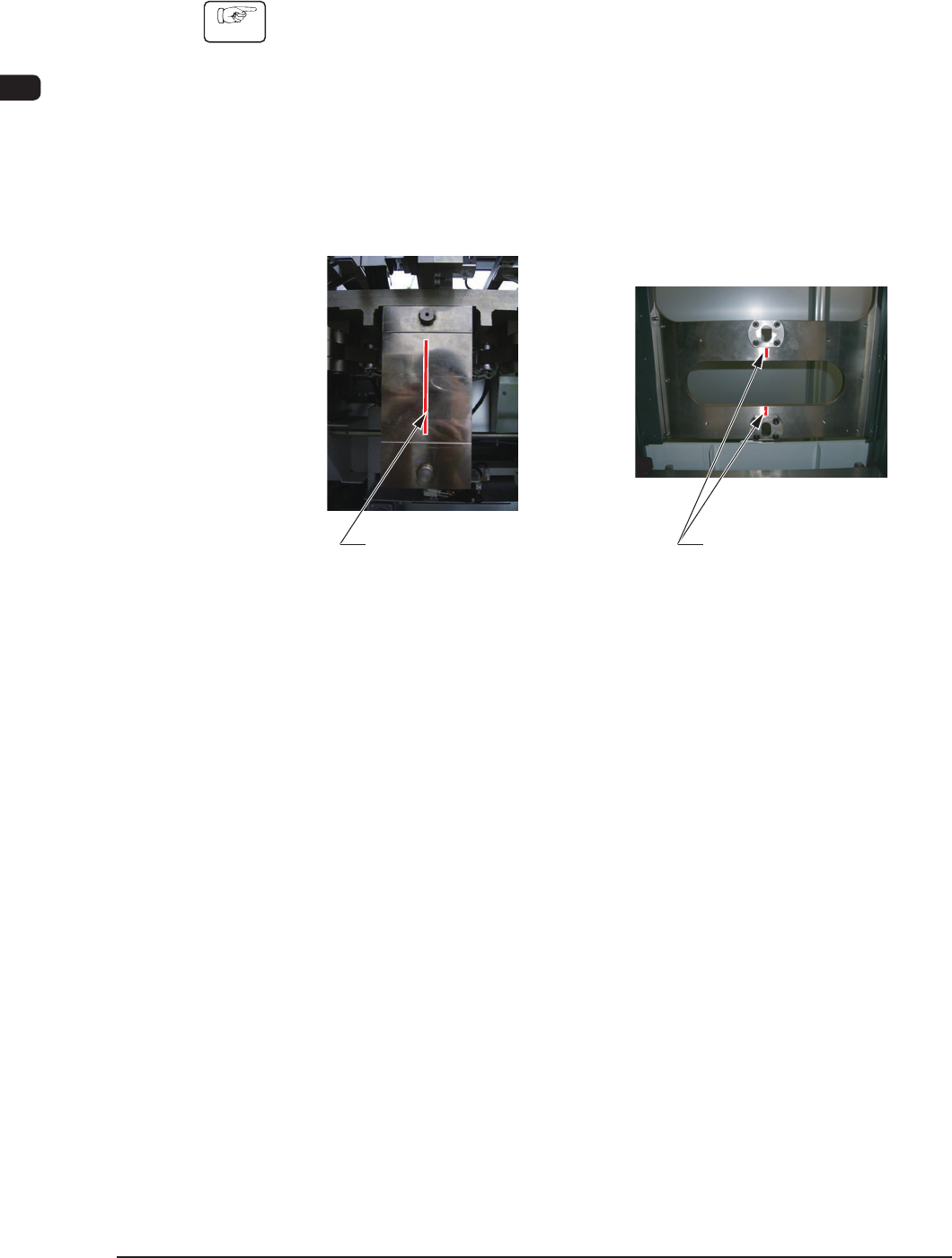
1.2.2.1 Elevator Height and Inclination Adjustment Procedures
•
Tools to be used
: Two Hook Spanners (Maintenance Tool Accessory)
Procedure
(1) Fix the traverse cart section onto the main machine installation section.
(2) Move the elevator unit to the attachment position.
(3) Adjust the elevator unit caster height to satisfy the following conditions.
(The bolt pitch in the caster section should be 3 mm / pitch).
•
The pilot pin on the side of the traverse cart should be located at the center
of the long hole section on the elevator side.
Positioning Pin on
the Traverse Cart Side
Long Hole Section on
the Elevator Side
Marking-off Line
on the Traverse Side
Marking-off Line
on the Elevator Side
F7C5
1003-002