7OM-1625-004_w.pdf - 第157页
7OM-1603 0908-001 5-B

7OM-1603
0908-001 5-A
Chapter 5
Supplement
This chapter describes the pneumatic diagrams, the parts location, the
location of sensors and loads, the electrical circuit diagrams, etc.
As this chapter contains highly sophisticated contents, it should carefully
be referred to.
1. Pneumatic Diagram
2. Layout of Sensors and Loads
3. Parts Location
4. Electrical Circuit Diagrams

7OM-1603
0908-001 5-B
7OM-1603
5-10908-001
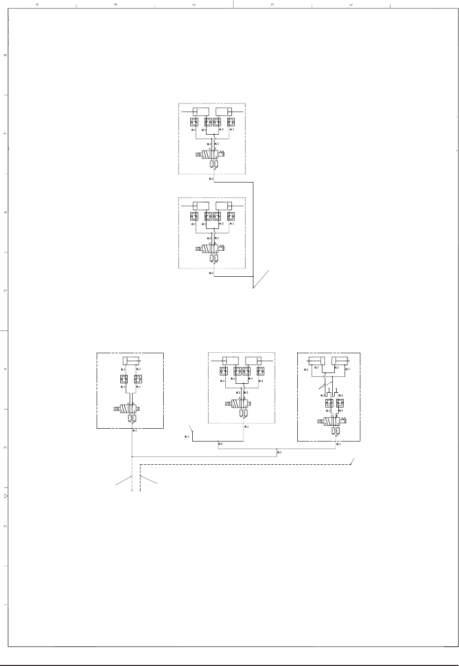
1. Pneumatic Diagram
1.1 Pneumatic Diagram (GS-FP100)
Elevator Axis 2 (Upper)
Rack Shutter (Upper)
Elevator Axis 1 (Lower)
Rack Shutter (Lower)
Traverse Unit
Pallet Chuck
Traverse Unit
EL Clamper
Traverse Unit
FD Clamper
Flux Application
Air Supply Socket
Elevator
Air Supply Socket
Bundled Connector Air Piping
(Arrangement No. 3)
Bundled Connector Air Piping
(Arrangement No. 1)
Traverse Cart
From the air supply socket
Elevator Unit Pneumatic Diagram
Traverse Cart Pneumatic Diagram
Flat Cable