00198500-02_VD_711.1_R18-1_DE_EN.pdf - 第13页
Station Software 71 1.1 (R18 - 1) / Versio n Description 05/2018 Edition 13 In the Maintenance tool, t he Level ing assistant button has b een added under Verification . By clicking this but ton, the new Leveli ng assist…
Station Software 711.1 (R18-1) / Version Description 05/2018 Edition
12
Figure 4-3: Activities – Manual Operations
Error messages related to the Linear Dipping Unit 2 X are displayed on the station software GUI
and, if necessary the machine is stopped.
Detailed information on the Linear Dipping Unit 2 X can be found in the Linear Dipping Unit 2 X
User Manual, item no. [00198517-xx].
4.6 Adjusting Z-Height of Vacuum Tooling
Compatible mode: Complete
The new conveyor in the SIPLACE CA4 V2 placement machine uses a motor driven lifting table. To
lift the vacuum tooling to the placement z-level, the conveyor control software determines the
correct z-height and moves the lifting table to this z-height. For this purpose, a measurement
sequence has been implemented that measures the actual height, aligns it with the expected
height, and, if necessary, sends a correction value to the conveyor control.
The transport control software uses two different offsets to correct the z-height of the vacuum
tooling: standard offset and mapping offset. The standard offset is used for boards with a thickness
<= 4.5 mm. The mapping offset is used for boards with a thickness > 4.5 mm, e.g. the mapping
board.
The station software provides four touchdown positions on the vacuum tooling surface to be used
for the height measurement. Those positions are available either in the four corners or on the main
axes through the center of the vacuum tooling surface.
Some settings can be made in the Service tool. This tool has been modified as follows:
– The standard offset is determined if Vacuum tooling calibration is selected under Automatic
calibration. The board thickness has to be entered manually (additional parameter Height of
board). The conveyor must be empty.
– The mapping offset is determined if Board mapping is selected under Automatic calibration.
No further entry is required.
– The (X, Y) touchdown points have been added to the conveyor section under Teaching
machine positions.
– Under Conveyor Configuration in the Vacuum tooling configuration, the user can enter for
which board thickness the adapter plate has been assigned. This facilitates the leveling.
Currently, there are two thicknesses: 1.2 mm and 0.55 mm.
Station Software 711.1 (R18-1) / Version Description 05/2018 Edition
13
In the Maintenance tool, the Leveling assistant button has been added under Verification. By
clicking this button, the new Leveling assistant view opens.
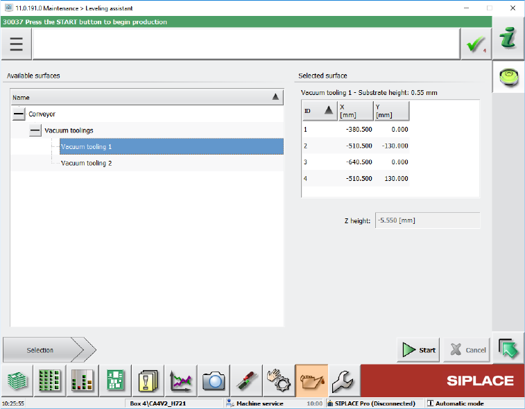
Figure 4-4: Leveling assistant view
The leveling assistant helps the user to adjust the z-height of the vacuum tooling. Additionally,
this tool is used to set up the planarity of the vacuum tooling surface and adjust it vertical to the
z-axes of the placement heads.
To the left, all available surfaces are displayed in a tree view. Currently, it contains entries for
adjusting the z-height of the vacuum tooling and measuring the height of the conveyor rail.
By selecting one of the available surfaces, a short description of the surface and a list of the
positions where the z-height will be measured are displayed to the right. The positions have the
same names as those that are used when the machine positions are taught. This makes it
easier for the user to identify the position in case it has to be taught or if the user e.g. wants to
check that the position is on the surface and not directly above a hole.
Station Software 711.1 (R18-1) / Version Description 05/2018 Edition
14
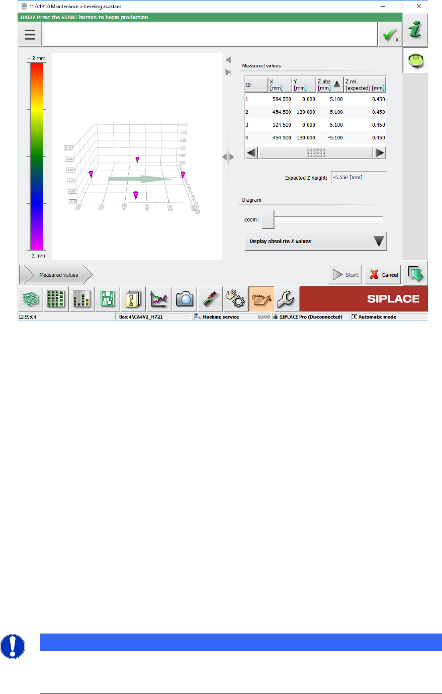
The measurement is started by pressing the Start button. If the measurement is successful, the
Measured values are displayed automatically. Otherwise an error message is displayed.
Figure 4-5: Measured values
In this view the measurement can be repeated at any time by pressing the Start button again.
An image displays the surface at the mean z-value, allowing the user to see which positions
are below or above the mean value. The user can select if the chart shall display absolute or
relative values. The relative values are always relative to the mean z-value.
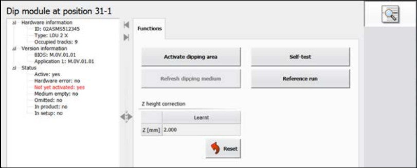
4.7 SIPLACE JTF-ML2 – Enhanced Functionality
The functionality has been enhanced for the SIPLACE JTF-ML2 tray feeder. The Manual
operations dialog for the feeder has been changed as follows:
– Functions dialog
Reset buttons have been added to the existing Transfer position – Teach position and Refill
position – Teach position functions for the lifting axes to reset the respective position to the
factory settings.
– New I/O ports dialog
The dialog displays the input and output states of the sensors. This dialog is only visible as of
activity level Machine service.
Additionally, the endurance run for trays has been added to the Maintenance – Endurance run
dialog for the SIPLACE JTF-ML2 feeder.
NOTICE
Manual functions are not prevented with components in the tray feeder. There is no
check in the station software. The operator is responsible for whether the tray feeder is
empty or not.