00196376-0102_UM S-Feeder_EN.pdf - 第51页
Tape Feeder Modules Setting the Step Size Details for 24/32, 44, 56, 72 and 88 mm S or S DP User Manual SIPLACE S-Feeder 51 2.4.3 Setting the Step Size To set the step size, proceed as follows: ► (1) Press the green &quo…
Tape Feeder Modules
Details for 24/32, 44, 56, 72 and 88 mm S or S DP Inserting the Tape
50 User Manual SIPLACE S-Feeder
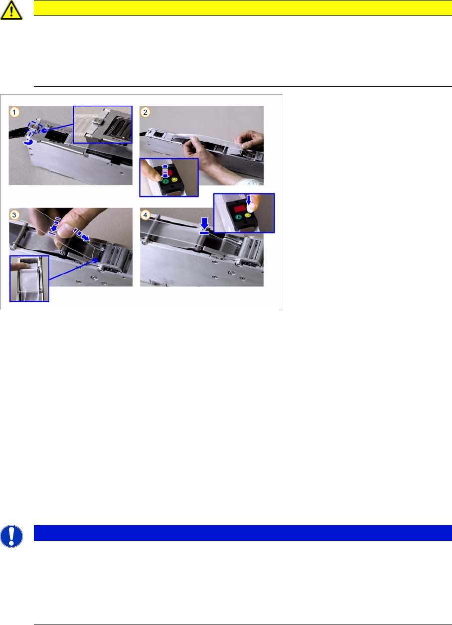
2.4.2.1 Inserting the Cover Tape in the Foil Removal
►(1) Close the pickup window, press it slightly downwards and hold.
Rotate the latch by 90° into its central position, so that it engages audibly. The pickup window is now
locked in place.
►(2) Press the green "Index" button until the tape comes out of the front of the feeder and then pull the
foil approx. 30 cm back.
►(3) Place the beginning of the foil over the foil rocker and then hold it between the two combing
toothed wheels of the foil removal device.
►(4) Press the yellow "Foil" button on the control unit and hold until the motor is switched off auto-
matically.
While you hold the button pressed and as long as the foil rocker is not tensioned, the motor will con-
tinue to draw in the foil. As the motor is not operated with full power in this case, you can adjust the
drawing in speed by gently tugging on the foil.
Make sure that the foil lies flat between the toothed wheels, that it has no folds and that it is not pulled
away to the sides of the toothed wheels.
CAUTION
Make sure that you remove the adhesive strip at the beginning of the cover tape overhang on
the new tapes. The adhesive strip could otherwise damage the foil removal. The same applies
to torn splice points. Remove any remaining adhesive strips here, before you feed the foil into
the foil container.
Do not tear the foil as a stretched foil could lead to malfunctions at the foil removal point.
NOTICE
Once the tape has been inserted and the cover tape tensioned, the pickup window may no long-
er be unlocked without first relieving the tension on the foil (by pressing rocker 2 and then wait-
ing until the foil motor has switched off). Nonobservance of this will cause the tape to be torn
out of its perforations by the tension applied to the foil and it to be moved forward by several
pockets.
The result: component losses and possible malfunctions from loose components.
Tape Feeder Modules
Setting the Step Size Details for 24/32, 44, 56, 72 and 88 mm S or S DP
User Manual SIPLACE S-Feeder 51
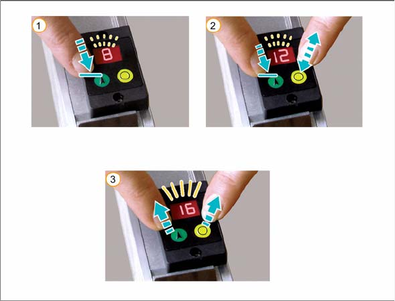
2.4.3 Setting the Step Size
To set the step size, proceed as follows:
►(1) Press the green "Index" button and hold until the LED display begins to flash. Continue to hold the
button pressed.
►(2) Press the yellow "Foil" button several times until the control unit display shows the required step
size in mm. The step size is increased by 4 mm each time you press the button.
If you accidentally exceed the required size, you can correct the setting using one of the following
options:
⇨ Press the yellow "Foil" button frequently, until the required step size is shown in the control unit
display.
Alternatively:
⇨ While you are in setting mode (display flashes), you can let go of the button and then press the
green button again (within one second) to reverse the direction of counting. The step size will
now be reduced by 4 mm each time you press the button.
You can reverse the direction of counting as often as you wish.
►Release both buttons.
The setting procedure is finished when the flashing display changes to a permanent display.
For an overview of the available step sizes, refer to "1.3 Technical Data" [ ➙ 10].
Tape Feeder Modules
Error Messages Error Messages for 3x8 mm S/SL
52 User Manual SIPLACE S-Feeder
2.5 Error Messages
2.5.1 Error Messages for 3x8 mm S/SL
All error messages are shown on the control unit display.
PFx (x = track 1, 2 or 3) pickup position incorrect
The drive has not reached its end position.
►Check the tape path (including the empty tape path) for any blockages or stiff movement.
►After fixing the error, acknowledge the error message by pressing the green "Index" button or the
yellow "Foil" button.
Fox (x = track 1, 2 or 3) foil error
▪ Foil torn:
– Insert the foil again and hold the yellow "Foil" button pressed until the motor switches off.
If the foil is tensioned correctly, the control unit display will change to show the set step size.
▪ Foil not removed:
– Press rocker 2 and wait until the foil motor switches off.
– Pull the foil out a little and then out from under the pickup window (you may need to open and
then close the pickup window).
– Tension the foil by pressing the yellow "Foil" button until the foil motor switches off.
If the foil is tensioned correctly, the control unit display will switch over to the set step size.
dAE data error
The feeder data storage process was not completed properly when the equipment was last switched off.
This display only appears for approx. 3 seconds at switch on.
Measure:
The feeder is defective and needs to be repaired.
CoE communication error
The feeder is unable to access data in the EEPROM. This display will only appear for approx. 3 seconds
at switch on.
Measure:
The feeder is defective and needs to be repaired.
Supply voltage (+30V DC) too low
The feeder is no longer ready for operation.
Measure:
Check whether this error message is caused by the FCU or by the feeder.
If multiple feeders on the same changeover table show this same error message, the FCU is probably
defective or the voltage supply to the FCU is faulty.
If only one feeder shows the above mentioned error message and if this message is also shown when
the feeder is connected to another changeover table, the feeder is defective and needs to be repaired.