00196376-0102_UM S-Feeder_EN.pdf - 第74页
Linear Vibratory Feeder, Typ e 3 Operating the Vibratory Feeder Cleaning the Component Stick Maga zines 74 User Manual SIPLACE S-Feeder 4.3.3 Cleaning the Comp onent Stick Magazines To ensure smooth component trans port,…
Linear Vibratory Feeder, Type 3
Fitting Component Stick Magazines onto the Feeder Operating the Vibratory Feeder
User Manual SIPLACE S-Feeder 73
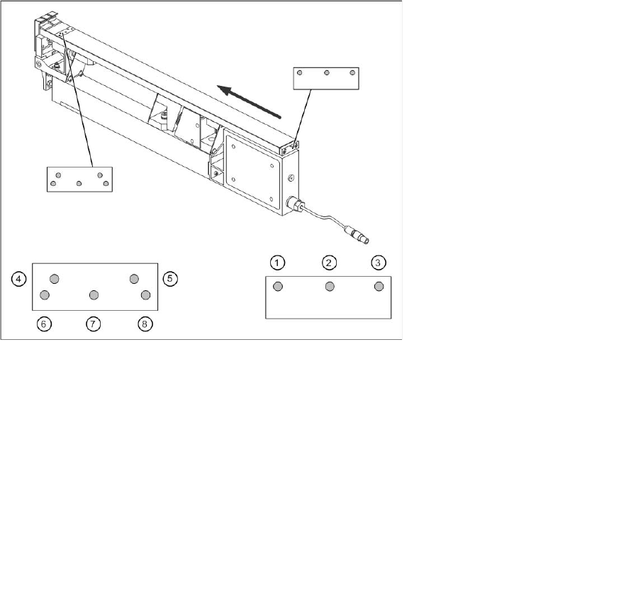
Legend:
Rear fixture position
1 Position for narrow and medium wide component stick magazines
2 Position for narrow and wide component stick magazines
3 Position for narrow and medium wide component stick magazines
Front fixture position
4 Position for medium wide component stick magazines
5 Position for medium wide component stick magazines
6 Position for narrow component stick magazines
7 Position for narrow and wide component stick magazines
8 Position for narrow component stick magazines
Linear Vibratory Feeder, Type 3
Operating the Vibratory Feeder Cleaning the Component Stick Magazines
74 User Manual SIPLACE S-Feeder
4.3.3 Cleaning the Component Stick Magazines
To ensure smooth component transport, make sure you clean the stick magazines at regular intervals
with a lint-free cloth and alcohol.
Dip Module
Area of Application
User Manual SIPLACE S-Feeder 75
5 Dip Module
5.1 Area of Application
To improve the solderability of corrosive components, for example, or of components with complex
structures, additional flux or conductive adhesive should be applied to these components. The medium
used should be applied to the components during placement. After pickup, the component is positioned
and then dipped in the medium with the help of a special feeder, the DIP module. This procedure is
known as component dipping.
The DIP module itself is set up on the changeover table, like the other feeders.
If the DIP module is not used for a period of several hours, we recommend removing the flux from the
module plate and cleaning the plate. This prevents the flux from becoming contaminated or its chemical
properties from changing. Please observe the manufacturer's specifications for the specific flux
concerned.
5.2 Structure
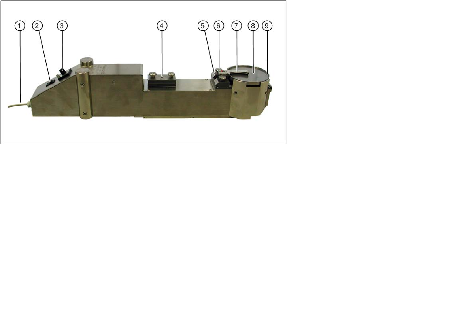
Overview: DIP module
The retrofitting kit consists only of the DIP module.
The DIP module is available as an option and can be ordered with the Item No. 00117010-xx.
Legend:
1 Power supply cable with Lemosa plug
2 Buttons
3 Potentiometer knob for setting the speed (with locking device)
4 Various intermediate plates (in park position); in version 2 only up to layer thickness of 75 µm
5 Intermediate plate currently in use
6 Knurled screws, squeegee fixture
7 Squeegee
8 Rotary plate with flux or conductive adhesive
9 Edge protection on rotary plate