00196376-0102_UM S-Feeder_EN.pdf - 第86页
Dip M odule Software Version 4xx (Platform 1) Configuring the DIP Module 86 User Manual SIPLACE S-Feeder 5.9.4.2 Recording the Z Position ► Determine the Z positi on by measuring the height difference fro m the input co …
Dip Module
Configuring the DIP Module Software Version 4xx (Platform 1)
User Manual SIPLACE S-Feeder 85
5.9.4 Configuring the DIP Module
The DIP module is only configured on the station computer. The following data is required:
Location and track: only one DIP module can be set up per machine.
The possible location is from track 7 to 111 (inclusive), whereby the specified track must correspond to
the electrical connection and be in the center of the module.
Coordinates for plate center in the machine coordinate system (X direction is PCB direction of transport,
Y direction is vertical to this and to the left, positive).
Z position of plate base. The zero point is the upper edge of the input conveyor, higher (positive) values
progress upwards. The plate base is lower than the conveyor, meaning that negative values need to be
entered.
5.9.4.1 Recording the X/Y Position
►Start SITEST from V 404.01.
►Determine the X and Y coordinates by moving the DIP module in SITEST.
Use the "LP-Kamera teachen" function to establish the X/Y coordinates in SITEST.
►To do this, position the camera on the center of the rotary plate. Make a note of the values so that
they can be entered in the station software.
NOTICE
Default = 0: with safety buffer of approx. 4000 mm
If the default value of 0 is kept, the path of 4000 mm will be travelled in slow Z axis mode. This
leads to minor loss of performance.
CAUTION
Type and source of the danger
SITEST may only be implemented by persons who have been trained to do so by ASM
Assembly Systems and who are therefore authorized to use the program.
NOTICE
Type and source of the danger
There are no single functions and SITEST functions available for the DIP module.

Dip Module
Software Version 4xx (Platform 1) Configuring the DIP Module
86 User Manual SIPLACE S-Feeder
5.9.4.2 Recording the Z Position
►Determine the Z position by measuring the height difference from the input conveyor upper edge to
the plate base with the axis test box e.g. with a C&P 6 or C&P 12 head:
Determining the Z axis position
►Open the SITEST menu C&P - Head Axes.
►Position the gantry manually over the DIP module.
►Release the Z axis.
►Move Z axis onto DIP plate.
►Read out axis position with axis test box or SITEST software and note.
►Switch Z axis on again.
►Position gantry manually over the conveyor (height measurement position).
►Release the Z axis.
►Move Z axis to conveyor edge.
►Read out axis position with axis test box or SITEST software and note.
►Switch Z axis on again.
Calculating the DIP module height
CP 6 / 12 placement head
(conveyor upper edge [digits] – plate base [digits])/ 44.42 = Z position [mm].
CAUTION
The following task may only be performed by persons who have been thoroughly trained to use
the
axis test box. Incorrect, negative Z values can cause damage to the components.
NOTICE
If the surface of the DIP plate is lower than the conveyor surface, you need to specify a negative
DIP height!
Dip Module
Activating the DIP Module Option Software Version 4xx (Platform 1)
User Manual SIPLACE S-Feeder 87
5.9.5 Activating the DIP Module Option
The DIP flux option is activated by an entry in the konfig.ma file (SRDaten\srcma\konfig.ma) on the
station computer.
▪ The value for the DIP flux switch needs to be set to 1 to activate the DIP flux function.
A value of 0 deactivates the DIP flux function.
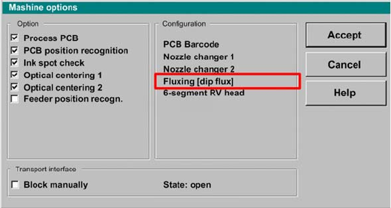
▪ After rebooting, you will see the entry:
"Fluxing[Dipflux]" and the corresponding pull down menus in the machine options.
User interface - machine options