00196376-0102_UM S-Feeder_EN.pdf - 第88页
Dip M odule Software Version 4xx (Platform 1) Data Input at Statio n Computer 88 User Manual SIPLACE S-Feeder 5.9.6 Data Input at Station Computer 5.9.6.1 Editing the Component Shape List ► Select: "Options" -&…
Dip Module
Activating the DIP Module Option Software Version 4xx (Platform 1)
User Manual SIPLACE S-Feeder 87
5.9.5 Activating the DIP Module Option
The DIP flux option is activated by an entry in the konfig.ma file (SRDaten\srcma\konfig.ma) on the
station computer.
▪ The value for the DIP flux switch needs to be set to 1 to activate the DIP flux function.
A value of 0 deactivates the DIP flux function.
▪ After rebooting, you will see the entry:
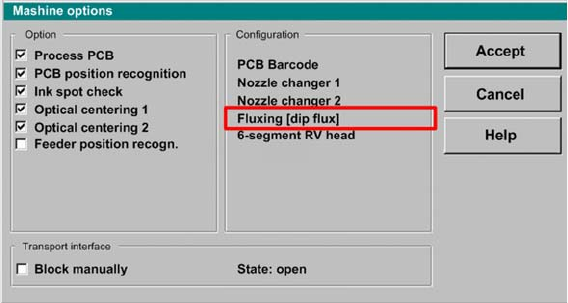
"Fluxing[Dipflux]" and the corresponding pull down menus in the machine options.
User interface - machine options
Dip Module
Software Version 4xx (Platform 1) Data Input at Station Computer
88 User Manual SIPLACE S-Feeder
5.9.6 Data Input at Station Computer
5.9.6.1 Editing the Component Shape List
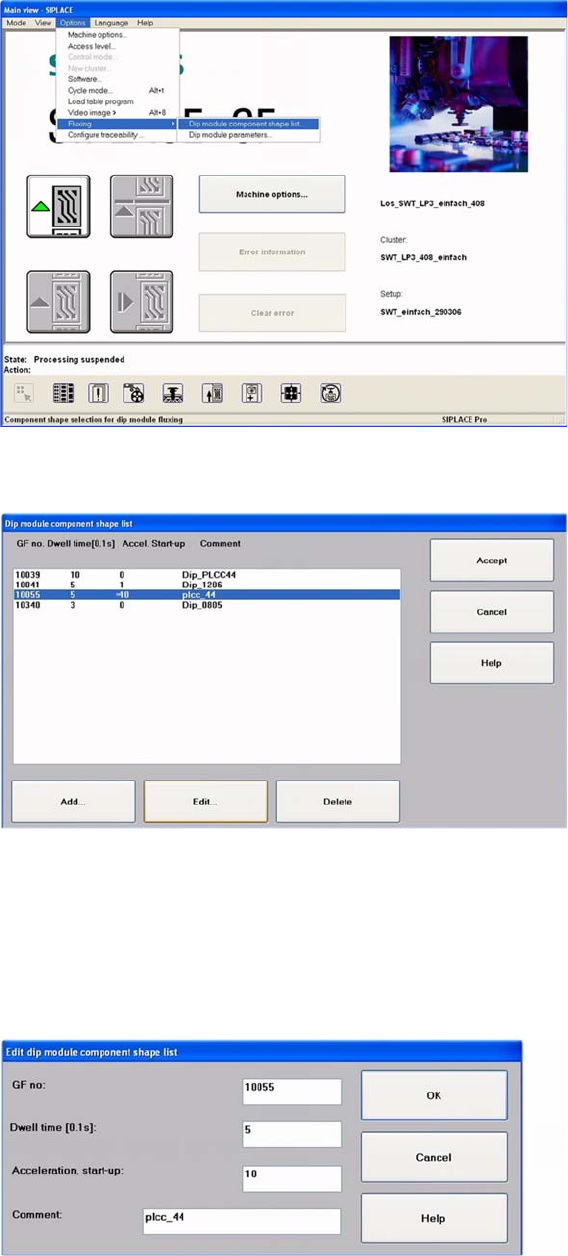
►Select:
"Options" -> "Fluxing" -> "Dip module CS list" from the menu.
User interface - selecting the component shape list for the DIP procedure
The DIP module component shape list will be shown.
DIP module - component shape list
►To add a new component, click on the "Add" button.
The following screen will be shown.
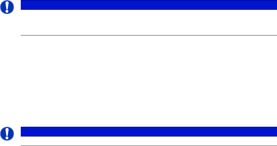
►To edit an existing or new component, mark the line concerned.
►Click on the Edit button, to edit an existing component shape.
The following dialog box will be shown.
DIP module component shape list: entering the "DIP module parameters"
Dip Module
Data Input at Station Computer Software Version 4xx (Platform 1)
User Manual SIPLACE S-Feeder 89
The following data needs to be entered:
CS Number:
The component shape number for the respective component
A component shape number between 1 and 32767 can be entered.
Dwell Time:
The time that the component is held on the board, in 1/10 seconds.
Values of 0 to 30 possible, for 0-3 s (typical: "10" for 1 sec.).
Acceleration for upwards travel
When the value is 0, the preset values from the line computer are used.
In this case, the Z axis moves up with the same acceleration used for lowering (downwards travel).
Enter a different value (other than 0) if you require slower upwards travel than that preset by the line
computer or SIPLACE Pro computer.
Valid values are those between 1 and 100.
When the value is not 0, the Z axis will move upwards from the DIP module plate with the specified per-
centage of the maximum Z axis acceleration.
Comments
You can enter a comment about the component concerned (e.g. PLCC).
Confirm you entry with OK.
Save the edited component shape list with Accept.
NOTICE
A change in the acceleration can be necessary, for example, if the component remains stuck
to the plate after dipping - as a result of low flux/conductive adhesive viscosity. a reduction in
the speed of upwards movement has a negative influence on placement performance.
NOTICE
Up to 25 component shapes can be entered for dipping in the station computer.