00196376-0102_UM S-Feeder_EN.pdf - 第76页
Dip M odule Safety Instructions 76 User Manual SIPLACE S-Feeder 5.3 Safety Instructions The place ment machine s in the SIP LACE family ar e powered by mai ns voltage. Parts of the machine may th erefore conduct dangerou…
Dip Module
Area of Application
User Manual SIPLACE S-Feeder 75
5 Dip Module
5.1 Area of Application
To improve the solderability of corrosive components, for example, or of components with complex
structures, additional flux or conductive adhesive should be applied to these components. The medium
used should be applied to the components during placement. After pickup, the component is positioned
and then dipped in the medium with the help of a special feeder, the DIP module. This procedure is
known as component dipping.
The DIP module itself is set up on the changeover table, like the other feeders.
If the DIP module is not used for a period of several hours, we recommend removing the flux from the
module plate and cleaning the plate. This prevents the flux from becoming contaminated or its chemical
properties from changing. Please observe the manufacturer's specifications for the specific flux
concerned.
5.2 Structure
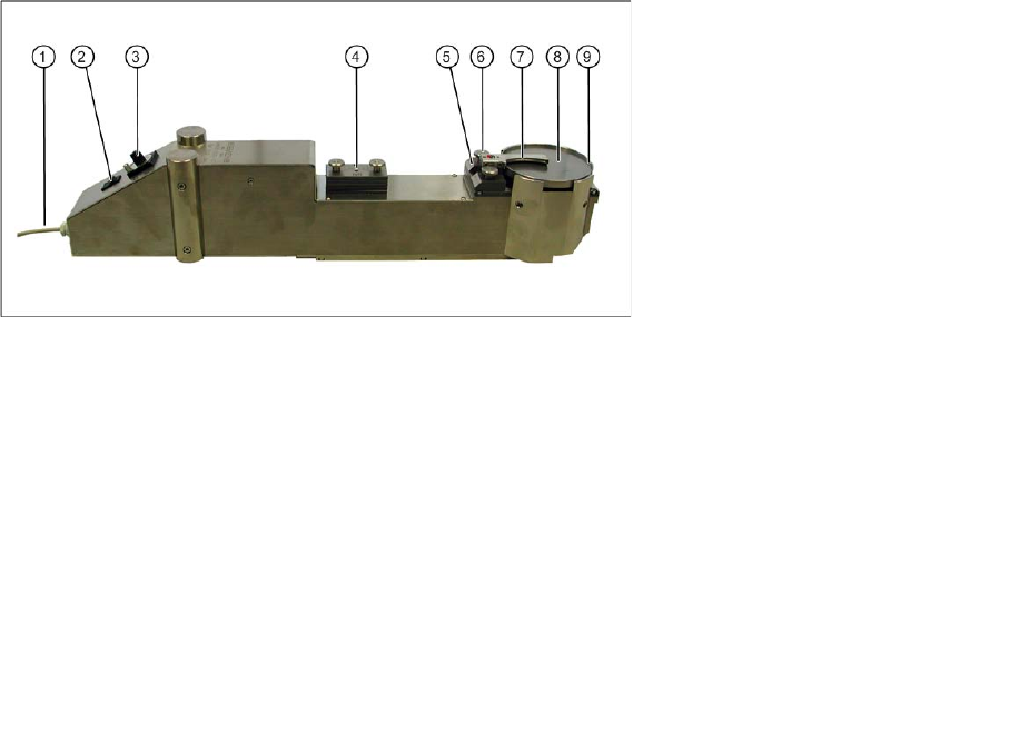
Overview: DIP module
The retrofitting kit consists only of the DIP module.
The DIP module is available as an option and can be ordered with the Item No. 00117010-xx.
Legend:
1 Power supply cable with Lemosa plug
2 Buttons
3 Potentiometer knob for setting the speed (with locking device)
4 Various intermediate plates (in park position); in version 2 only up to layer thickness of 75 µm
5 Intermediate plate currently in use
6 Knurled screws, squeegee fixture
7 Squeegee
8 Rotary plate with flux or conductive adhesive
9 Edge protection on rotary plate

Dip Module
Safety Instructions
76 User Manual SIPLACE S-Feeder
5.3 Safety Instructions
The placement machines in the SIPLACE family are powered by mains voltage. Parts of the machine
may therefore conduct dangerous voltage levels. This electricity is present at certain assemblies inside
the machine even when the main switch is switched off!
Incorrect use of the machine or touching live machine parts can cause fatal or severe injuries and con-
siderable damage to equipment.
After you have shut the operating system down properly and before you perform any work on the
machine, make sure that the placement machine has been turned off at the main switch and is isolated
from the mains power supply. In addition, the compressed air supply must be turned off at the main valve
of the compressed air unit in the machine base and the compressed air lines need to have been bled by
actuating the needle valve at the compressed air unit.
Danger: persons wearing a heart pacemaker are not permitted to work near linear motors, as described
in detail in the placement machine operating and service manuals, chapter "Special Safety instructions
for Working in the Vicinity of Powerful Magnetic Fields".
Observe the applicable accident prevention regulations, DIN standards and special safety regulations
applicable for your country at all times.
Observe the ESD regulations and the instructions about residual voltage in the chapter "Operating
safety" of the operating manual.
Before performing any retrofitting work on the placement machine, secure it to prevent unauthorized
reactivation or use by other persons.
There is an additional, higher risk of accidents when working with the SITEST program. The SITEST
program may therefore only be started by specially authorized and trained persons.
WARNING
The safety instructions in the chapter Operating Safety of the operating manual and the service
manual take precedence.
NOTICE
Also observe the safety instructions at the beginning of this manual.
Dip Module
Hand Guards
User Manual SIPLACE S-Feeder 77
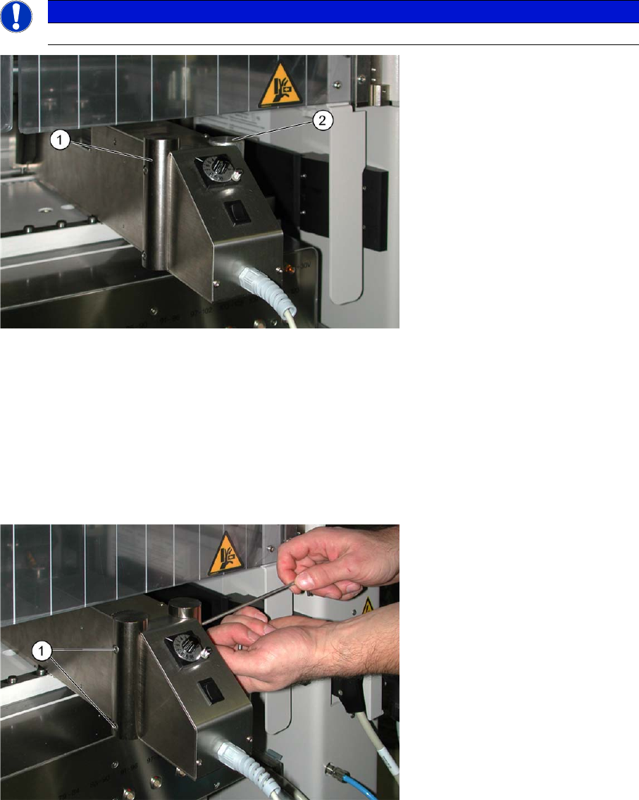
5.4 Hand Guards
The DIP module is set up like a feeder on the changeover table. As with a feeder, the DIP module needs
to be protected above to prevent unauthorized access. To achieve this, one of two hand guards - the
specific version depends on the machine type - must be fitted on the DIP module.
As a default, the DIP module is supplied with the high hand guard and can therefore be set up in all
SIPLACE placement machines except D1/D2.
The short hand guard supports supplied need to be used instead of the high ones when working with
D1/D2 machines.
To change the hand guards, proceed as follows:
►Loosen the two screws attached to both sides of the DIP module (1).
►Remove the hand guard.
►Fit the other hand guard on both sides of the DIP module.
NOTICE
Observe the warnings on the DIP module.
Legend:
1 High hand guard – for all SIPLACE placement machines except D1 /D2
2 Low hand guard – for D1/D2 SIPLACE placement machines