00196376-0102_UM S-Feeder_EN.pdf - 第83页
Dip Module Restrictions Software Version 4xx (Platform 1) User Manual SIPLACE S-Feeder 83 5.9 Software Version 4xx (Platform 1) 5.9.1 Restrictions The placement performance of the machine is limited by the DIP module. On…
Dip Module
Software Version 5xx / 6xx (Platform 2) Configuring the DIP Module
82 User Manual SIPLACE S-Feeder
5.8.4 Configuring the DIP Module
The DIP modules can only be configured on the SIPLACE Pro computer. The following data is required:
Location and track
Only one DIP module can be set up at each location (a maximum of three per machine). The available
tracks are from 13 to 55. The track specified must be the left edge of the DIP module.
X-Y position of the DIP module
The X/Y position of the DIP module is recognized during track programming on the changeover table.
Z position of DIP module
The Z position of the DIP module is recognized by the design of the module.
Programming the DIP parameters
The following DIP parameters can be set in the "Advanced Handling " menu of the SIPLACE Pro
Component Shape Editor:
▪ Order of dipping and optical centering
▪ DIP time (in ms) for component shape
▪ The largest square component (2) to be dipped is 24.55x24.55mm
▪ The largest connector can be 60 mm long, with a width of 14.1 mm.
The rotation time for the DIP plate is
▪ Limited to a maximum of 15 s in the station.
▪ Preset in SIPLACE Pro (2000 ms).
Set the speed on the DIP module so that a complete rotation of the DIP plate is possible within this
time.
Programming the placement parameters for dipped components
It may be advisable to hold the component on the PCB for a brief moment during placement.
The waiting time (in ms; typically: 100 ms) can be programmed in the "Advanced Handling" menu of the
Component Shape Editor during the placement process.
Troubleshooting and individual DIP module functions
To see whether dipping is performed, a vacuum check can be run before the Z axis is positioned down-
wards.
After dipping, a vacuum check can be run again to see whether the component was lost in the DIP
module. If a component was lost in the DIP module, the DIP module status will be set to "Defective"
Dipping will not be continued until the DIP module is reactivated by the operator.
To reactivate the module, the operator must remove the component manually and trigger plate rotation
to circulate the dipping medium.
Omitting components
▪ If a component to be dipped is omitted due to a DIP error, all components to be dipped with this
module will be omitted.
▪ If a component to be dipped is omitted due to a track error, only this specific component will be
omitted.
Dip Module
Restrictions Software Version 4xx (Platform 1)
User Manual SIPLACE S-Feeder 83
5.9 Software Version 4xx (Platform 1)
5.9.1 Restrictions
The placement performance of the machine is limited by the DIP module.
Only DIP modules with circular plates are supported.
The DIP module itself (HW) does not report any errors (non-intelligent feeder) i.e. the software is unable
to determine whether a DIP module is connected or whether the rotary movement of the plate was
successful or not.
When dipping components, no placement data is generated for user information (OIS and MaDaMaS).
The use of feeder cover plates is not possible with DIP modules.
Dipping is possible
▪ With the P&P placement head (with all SW versions)
▪ With a C&P 6 head on a gantry (with all SW versions).
▪ With a C&P 12 head on a gantry (from SW version 408).
Only one DIP module can be used per placement machine.
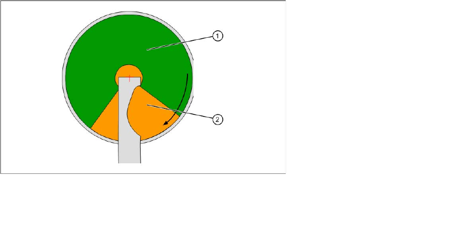
5.9.2 Module Function
The whole diameter of the plate is not available for dipping. This is partially restricted by the squeegee.
In addition, dipping may not be performed directly next to the squeegee for technical reasons, causing
excess medium to collect in 4 areas (on the bottom right of the DIP plate).
For these reasons, the area available for dipping is defined via the parameters R1, R2, Phi1 and Ph2.
Dipping area on a module
▪ The DIP module can be set up at all locations.
▪ C&P6 and C&P 12 (408 only) placement heads work according to the "Dipping before Vision"
principle. When using the P&P head, "Vision before dipping" is also possible.
▪ The DIP position is a fixed setting on the rotary plate.
Legend:
1 DIP area
2 Refill area
Dip Module
Software Version 4xx (Platform 1) Integration in the Overall System
84 User Manual SIPLACE S-Feeder
5.9.3 Integration in the Overall System
SIPLACE Pro
Component Editor:
Entries in the Component Editor are not transmitted to the station with software version 4xx.
Component Shape Editor:
Entries in the Component Shape Editor are not transmitted to the station with software version 4xx.
Setup:
Only one DIP module can be set up per placement machine.
▪ In station software versions up to 407 the programmer must keep the location (18 tracks) manually
free for a DIP module.
▪ From station software versions 408 (SIPLACE Pro 3.2) the DIP module can be programmed on a
specific table, to ensure that this location is not blocked by other feeders.
Station computer
The GUI provides the following user interfaces which are relevant for the DIP module:
▪ New display view, programming and operation of the DIP module
▪ Error messages relating to the DIP module in the error line and in the "Error display" view
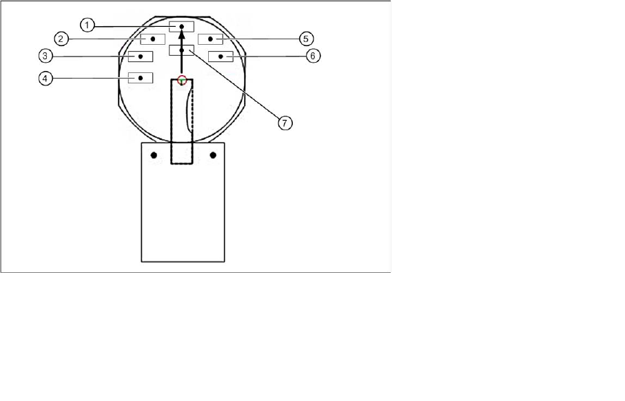
Hardware
The layer height is set at the DIP module with the help of a metal disk. The medium is applied manually
be the operator. The DIP module has a lockable potentiometer for setting the rotation speed and a button
for starting plate rotation.
Legend:
1 Position S1 5 Position S5
2 Position S2 6 Position S6
3 Position S3 7 Position IC
4 Position S4