Samsung(三星)-KLM8G1GEAC-B001.pdf - 第16页
- 15 - IF THERE IS ANY OTHER OPERATION TO IMPLEMENT IN ADDITION TO SPECIFICATION IN THE DATASHEET OR JEDEC STANDARD, PLEASE CONTACT EACH BRANCH OFFICE OR HEADQUARTERS OF SAMSUNG ELECTRONICS. datasheet e·MMC Rev. 1.0 KLMx…
- 14 -
IF THERE IS ANY OTHER OPERATION TO IMPLEMENT IN ADDITION TO SPECIFICATION
IN THE DATASHEET OR JEDEC STANDARD, PLEASE CONTACT EACH BRANCH OFFICE OR
HEADQUARTERS OF SAMSUNG ELECTRONICS.
datasheet
e·MMC
Rev. 1.0
KLMxGxGEAC-B001
SAMSUNG CONFIDENTIAL
4.5 Power Off Notification
Device has no idea when host powers off. Power Off Notification allows the host to notify the device before the host powers off. This enables the device to
better prepare itself for being powered off. This feature can be used by the host to write meta data in advance that can reduce initialization time in the next
power up sequence.
[Power Off Notification sequence]
If the power off notification is supported by host, the host shall first set
POWER_OFF_NOTIFICATION byte in EXT_CSD [34] to POWERED_ON (0x01)
Before powering the device down, the host will change the value to either
POWER_OFF_SHORT (0x02) or POWER_OFF_LONG (0x03)
[Power Off Notification Mode]
The difference between two types of Power Off modes is that how quickly host wants to turn power off.
1) Power Off Long (0x03) : The device should respond to POWER_OFF_LONG_TIME timeout if more time for power off is acceptable.
2) Power Off Short (0x02) : The device should respond to POWER_OFF_SHORT under the Generic CMD6 timeout.
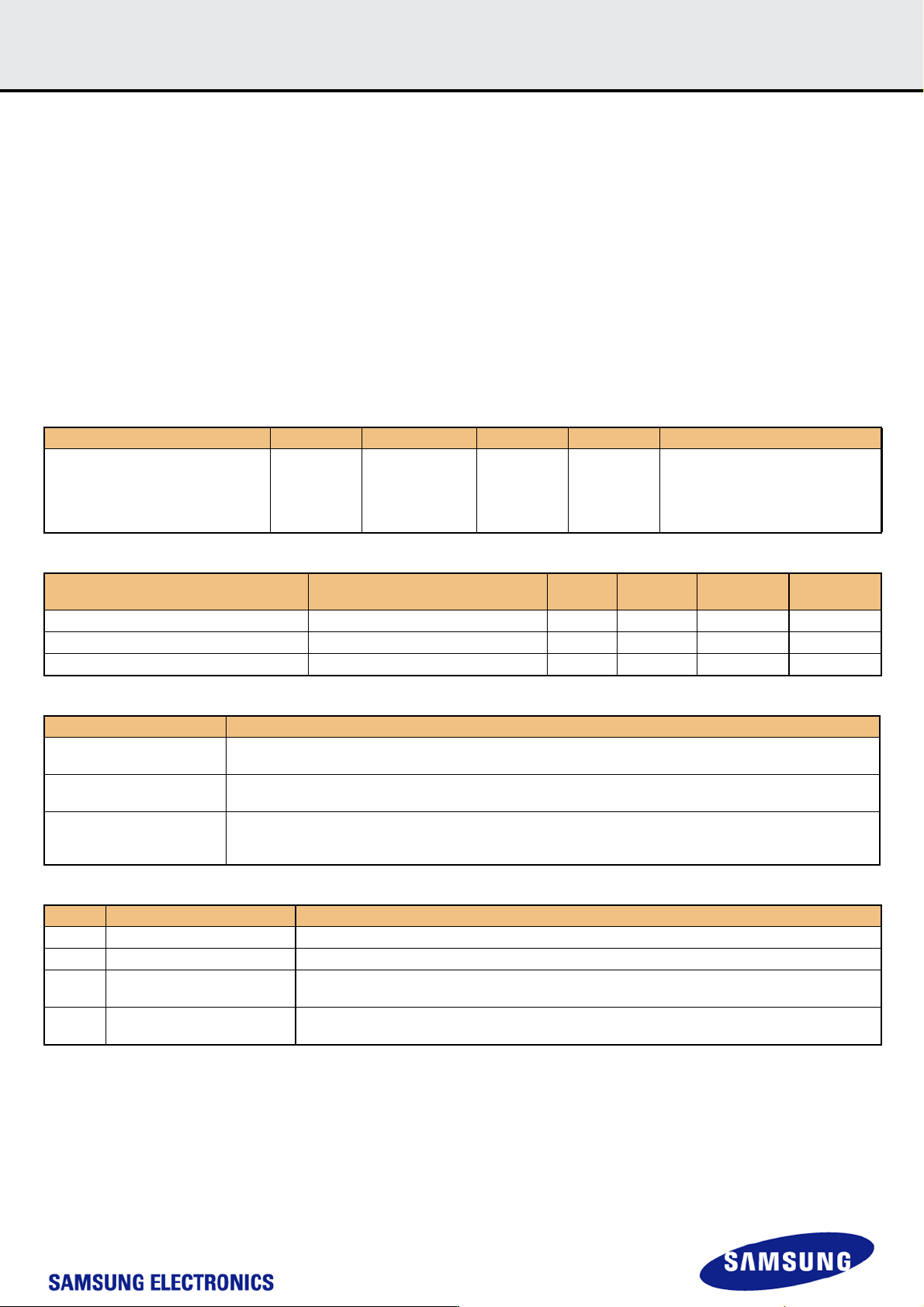
[Table 17] Command description related to Power Off Notification
[Table 18] EXT_CSD value for Power Off Notification
[Table 19] Definition of EXT_CSD value for Power Off Notification
[Table 20] Valid POWER_OFF_NOTIFICATION values
CMD INDEX Type Argument Resp Abbreviation Command Description
CMD6 ac
[25:24] Access
[23:16] Index
[15:8] Value
[7:3] Set to 0
[2:0] CMD set
R1b SWITCH
Switches the mode of operation of the
selected Device or modifies the
EXT_CSD registers.
Name Field
Size
(Bytes)
Cell
Type
CSD-Slice Value
Generic CMD6 timeout GENERIC_CMD6_TIME 1 R [248] 0x0A
Power off notification(long) timeout POWER_OFF_LONG_TIME 1 R [247] 0x3C
Power Off Notification POWER_OFF_NOTIFICATION 1 R/W/E_P [34] 0x00
Field Definition
GENERIC_CMD6_TIME
(Power off short)
The default max. timeout for a SWITCH command (CMD6)
Generic CMD6 timeout = 10ms x GENERIC_CMD6_TIME
POWER_OFF_LONG_TIME
Max. timeout for the SWITCH command (CMD6) when notifying the device that the power is about to be turned off.
Power off long timeout = 10ms x POWER_OFF_LONG_TIME
POWER_OFF_NOTIFICATION
This field allows host to notify the device when the host powers off.
Any other values which don’t exist in the [Table 3] are invalid. If the host sets invalid values, the device will result in
SWITCH_ERROR.
Value Name Description
0x00 NO_POWER_NOTIFICATION Power off notification is not supported by host, device shall not assume any notification.
0x01 POWERED_ON Host shall notify before powering off the device, and keep power supplies alive and active until then.
0x02 POWER_OFF_SHORT
Host is going to power off the device. The device
shall respond within GENERIC_CMD6_TIME.
0x03 POWER_OFF_LONG.
Host is going to power off the device. The device
shall respond within POWER_OFF_LONG_TIME

- 15 -
IF THERE IS ANY OTHER OPERATION TO IMPLEMENT IN ADDITION TO SPECIFICATION
IN THE DATASHEET OR JEDEC STANDARD, PLEASE CONTACT EACH BRANCH OFFICE OR
HEADQUARTERS OF SAMSUNG ELECTRONICS.
datasheet
e·MMC
Rev. 1.0
KLMxGxGEAC-B001
SAMSUNG CONFIDENTIAL
5.0 Technical Notes
5.1 S/W Agorithm
5.1.1 Partition Management
The device initially consists of two Boot Partitions and RPMB Partition and User Data Area.
The User Data Area can be divided into four General Purpose Area Partitions and User Data Area partition. Each of the General Purpose Area partitions
and a section of User Data Area partition can be configured as enhanced partition.
5.1.1.1 Boot Area Partition and RPMB Area Partition
Boot Partition size & RPMB Partition Size are set by the following command sequence :
[Table 21] Setting sequence of Boot Area Partition size and RPMB Area Partition size
Boot partition size is calculated as ( 128KB * BOOT_SIZE_MULTI )
The size of Boot Area Partition 1 and 2 can not be set independently. It is set as same value.
RPMB partition size is calculated as ( 128KB * RPMB_SIZE_MULTI ).
In RPMB partition, CMD 0, 6, 8, 12, 13, 15, 18, 23, 25 are admitted.
Access Size of RPMB partition is defined as the below:
[Table 22] REL_WR_SEC_C value for write operation on RPMB partition
Any undefined set of parameters or sequence of commands results in failure access.
If the failure is in data programming case, the data is not programmed. And if the failure occurs in data read case, the read data is ‘0x00’.
5.1.1.2 Enhanced Partition (Area)
SAMSUNG e·MMC adopts Enhanced User Data Area as SLC Mode. Therefore when master adopts some portion as enhanced user data area in User
Data Area, that area occupies double size of original set up size. ( ex> if master set 1MB for enhanced mode, total 2MB user data area is needed to gen-
erate 1MB enhanced area)
Max Enhanced User Data Area size is defined as (MAX_ENH_SIZE_MULT x HC_WP_GRP_SIZE x HC_ERASE_GRP_SIZE x 512kBytes)
Function Command Description
Partition Size Change Mode CMD62(0xEFAC62EC) Enter the Partition Size Change Mode
Partition Size Set Mode CMD62(0x00CBAEA7) Partition Size setting mode
Set Boot Partition Size CMD62(BOOT_SIZE_MULTI) Boot Partition Size value
Set RPMB Partition Size CMD62(RPMB_SIZE_MULTI)
RPMB Partition Size value
F/W Re-Partition is executed in this step.
Power Cycle
REL_WR_SEC_C Description
REL_WR_SEC_C = 1 Access sizes 256B and 512B supported to RPMB partition
REL_WR_SEC_C > 1 Access sizes up to REL_WR_SEC_C * 512B supported to RPMB partition with 256B granularity
- 16 -
IF THERE IS ANY OTHER OPERATION TO IMPLEMENT IN ADDITION TO SPECIFICATION
IN THE DATASHEET OR JEDEC STANDARD, PLEASE CONTACT EACH BRANCH OFFICE OR
HEADQUARTERS OF SAMSUNG ELECTRONICS.
datasheet
e·MMC
Rev. 1.0
KLMxGxGEAC-B001
SAMSUNG CONFIDENTIAL
5.1.2 Boot operation
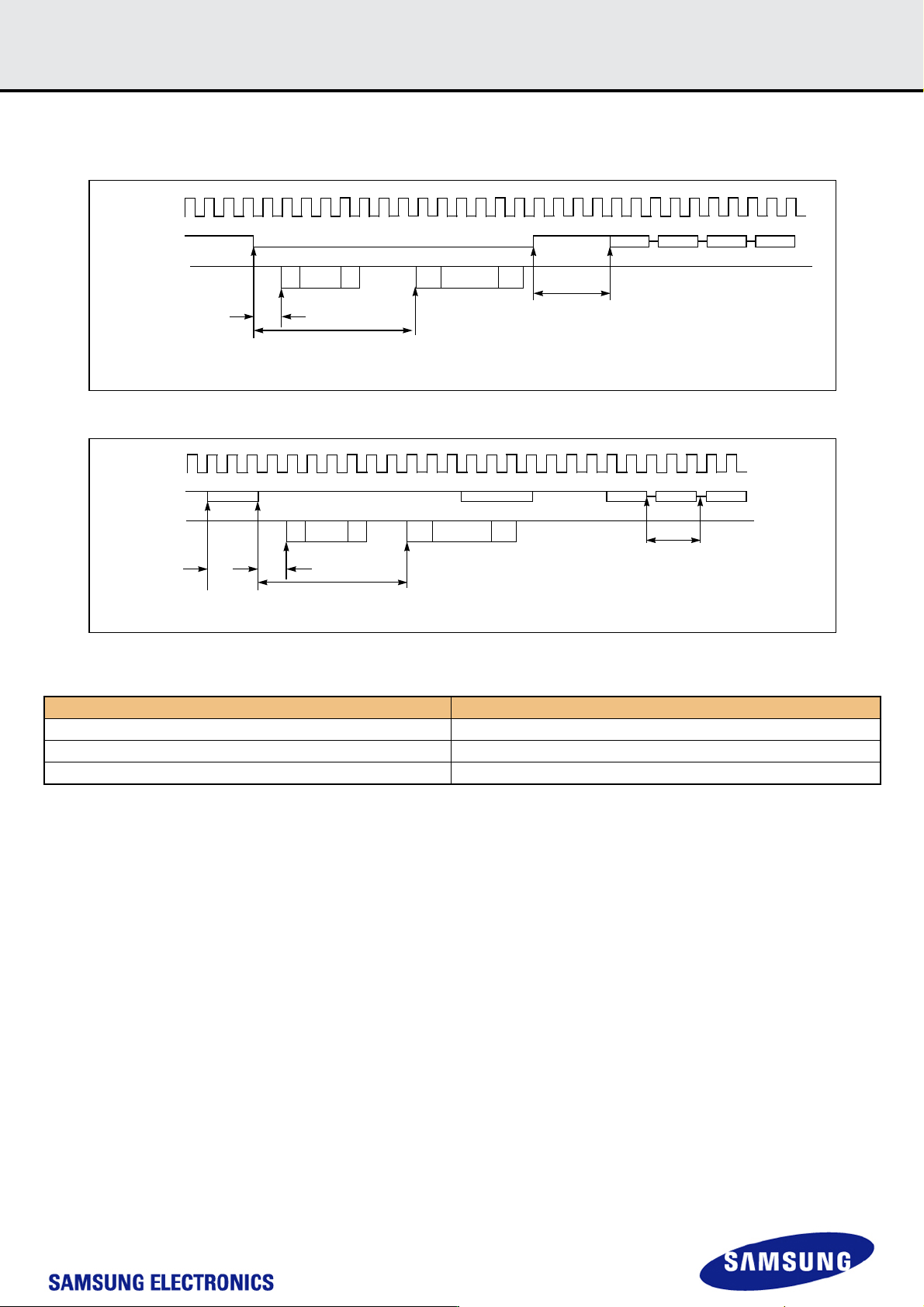
Device supports not only boot mode but also alternative boot mode. Device supports high speed timing and dual data rate during boot.
Figure 5. MultiMediaCard state diagram (boot mode)
Figure 6. MultiMediaCard state diagram (alternative boot mode)
[Table 23] Boot ack, boot data and initialization Time
NOTE:
1) This initialization time includes partition setting, Please refer to INI_TIMEOUT_AP in 6.4 Extended CSD Register.
Normal initialization time (without partition setting) is completed within 1sec
Timing Factor Value
(1) Boot ACK Time < 50 ms
(2) Boot Data Time < 60 ms
(3) Initialization Time
1)
< 3 secs
SE
SE
010
512bytes
+CRC
CLK
CMD
DAT[0]
CMD1 RESP CMD2 RESP
Boot terminated
MIn 8 cloks + 48 clocks = 56 clocks required from
CMD signal high to next MMC command.
(1)
(2)
*(1) Boot ACK Time (2) Boot Data Time (3) CMD1 Time
SE
SE
010
512bytes
+CRC
CLK
CMD
DAT[0]
CMD1
RESP CMD2
CMD0
1
CMD0 Reset
Min74
Clocks
required
after
power is
stable to
start boot
command
*(1) Boot ACK Time (2) Boot Data Time (3) CMD1 Time
*CMD0 with argument 0xFFFFFFFA
(1)
(2)
Boot terminated
CMD1
(3)