Samsung(三星)-KLM8G1GEAC-B001.pdf - 第26页
- 25 - IF THERE IS ANY OTHER OPERATION TO IMPLEMENT IN ADDITION TO SPECIFICATION IN THE DATASHEET OR JEDEC STANDARD, PLEASE CONTACT EACH BRANCH OFFICE OR HEADQUARTERS OF SAMSUNG ELECTRONICS. datasheet e·MMC Rev. 1.0 KLMx…
- 24 -
IF THERE IS ANY OTHER OPERATION TO IMPLEMENT IN ADDITION TO SPECIFICATION
IN THE DATASHEET OR JEDEC STANDARD, PLEASE CONTACT EACH BRANCH OFFICE OR
HEADQUARTERS OF SAMSUNG ELECTRONICS.
datasheet
e·MMC
Rev. 1.0
KLMxGxGEAC-B001
SAMSUNG CONFIDENTIAL
NOTE :
1) Reserved bits should read as “0.”
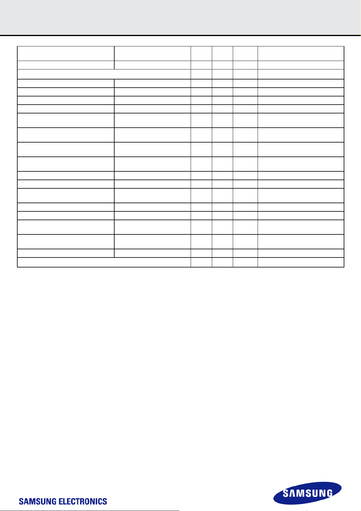
High Performance Mode Configuration HIGH_PERF_CONFIG 1
R/W/
E_P
[68] 0x00
Auto Background Operation Configuration AUTO_BKOP_CONFIG 1 R/W/E [67] 0x00
Reserved
1
1 - [66] -
Optimized Features OPTIMIZED_FEATURES 2 R [65:64] 0x0F
Native sector size NATIVE_SECTOR_SIZE 1 R [63] 0x00
Sector size emulation USE_NATIVE_SECTOR 1 R/W [62] 0x00
Sector size DATA_SECTOR_SIZE 1 R [61] 0x00
1st initialization after disabling sector size
emulation
INI_TIMEOUT_EMU 1 R [60] 0x00
Class 6 commands control CLASS_6_CTRL 1
R/W/
E_P
[59] 0x00
Number of addressed group to be
Released
DYNCAP_NEEDED 1 R [58] 0x00
Exception events control EXCEPTION_EVENTS_CTRL 2
R/W/
E_P
[57:56] 0x00
Exception events status EXCEPTION_EVENTS_STATUS 2 R [55:54] 0x00
Extended Partitions Attribute EXT_PARTITIONS_ATTRIBUTE 2 R/W [53:52] 0x00
Context configuration CONTEXT_CONF 15
R/W/
E_P
[51:37] 0x00
Packed command status PACKED_COMMAND_STATUS 1 R [36] 0x00
Packed command failure index PACKED_FAILURE_INDEX 1 R [35] 0x00
Power Off Notification POWER_OFF_NOTIFICATION 1
R/W/
E_P
[34] 0x00
Control to turn the Cache ON/OFF CACHE_CTRL 1
R/W/
E_P
[33] 0x00
Flushing of the cache FLUSH_CACHE 1 W/E_P [32] 0x00
Reserved
1
32 - [31:0] -
- 25 -
IF THERE IS ANY OTHER OPERATION TO IMPLEMENT IN ADDITION TO SPECIFICATION
IN THE DATASHEET OR JEDEC STANDARD, PLEASE CONTACT EACH BRANCH OFFICE OR
HEADQUARTERS OF SAMSUNG ELECTRONICS.
datasheet
e·MMC
Rev. 1.0
KLMxGxGEAC-B001
SAMSUNG CONFIDENTIAL
7.0 AC PARAMETER
7.1 Timing Parameter
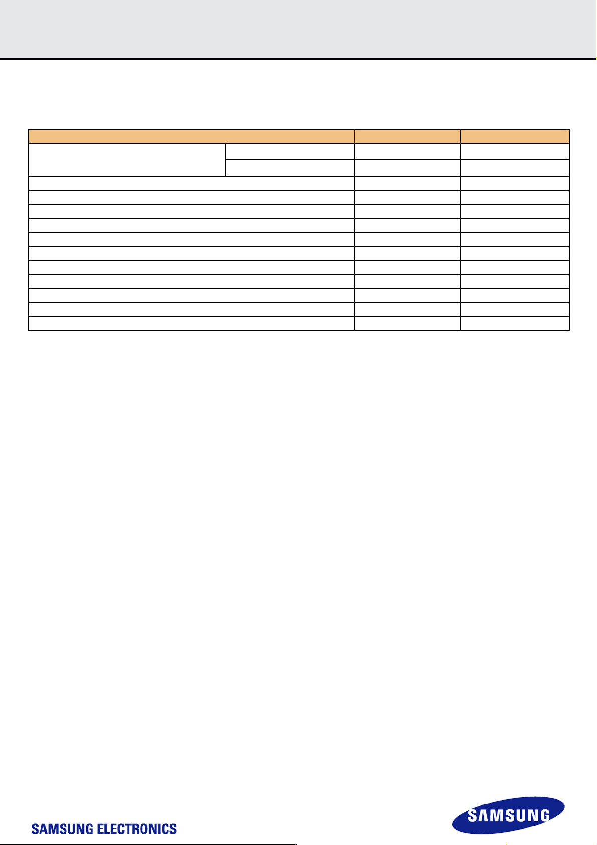
[Table 35] Timing Parameter
NOTE:
1) Normal Initialization Time without partition setting
2) Initialization Time after partition setting, refer to INI_TIMEOUT_AP in 6.4 EXT_CSD register
3) Timeout values are measured based on Samsung's test pattern
4) Under severe user cases, EXCEPTION_EVENT occurs and Timeout values have possibility to increase
7.2 Previous Bus Timing Parameters for DDR52 are defined by JEDEC standard
Timing Paramter Max. Value Unit
Initialization Time (tINIT)
Normal
1)
1s
After partition setting
2)
3s
Read Timeout 100 ms
Write Timeout 350 ms
Erase Timeout 20 ms
Force Erase Timeout 3 min
Secure Erase Timeout 8s
Secure Trim step1 Timeout 5s
Secure Trim step2 Timeout 3s
Trim Timeout 600 ms
Partition Switching Timeout (after Init) 100 us
Power Off Notification (Short) Timeout 100 ms
Power Off Notification (Long) Timeout 600 ms
- 26 -
IF THERE IS ANY OTHER OPERATION TO IMPLEMENT IN ADDITION TO SPECIFICATION
IN THE DATASHEET OR JEDEC STANDARD, PLEASE CONTACT EACH BRANCH OFFICE OR
HEADQUARTERS OF SAMSUNG ELECTRONICS.
datasheet
e·MMC
Rev. 1.0
KLMxGxGEAC-B001
SAMSUNG CONFIDENTIAL
7.3 Bus Timing Specification in HS200 mode
7.3.1 HS200 Clock Timing
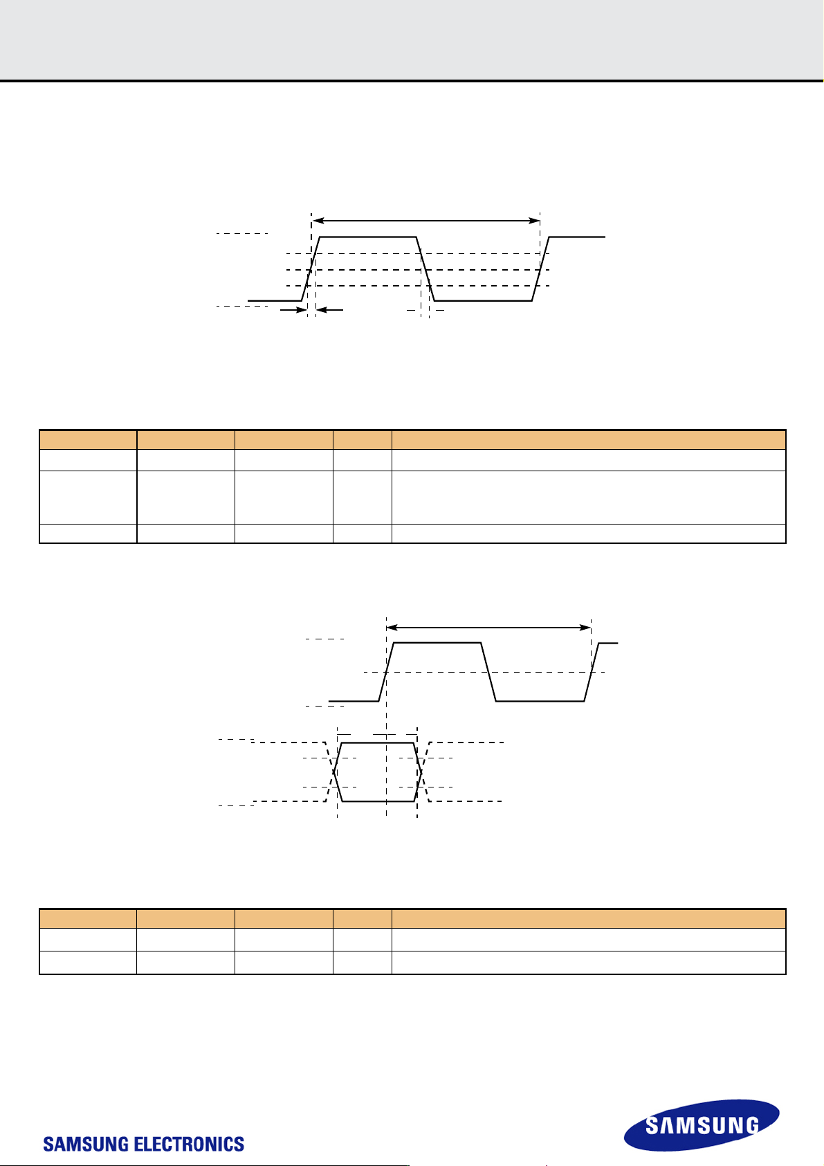
Host CLK Timing in HS200 mode shall conform to the timing specified in Figure 7 and Table 37. CLK input shall satisfy the clock timing over all possible
operation and environment conditions.CLK input parameters should be measured while CMD and DAT lines are stable high or low, as close as possible
to the Device. The maximum frequency of HS200 is 200MHz. Hosts can use any frequency up to the maximum that HS200 mode allows.
Figure 7. HS200 Clock signal timing
NOTE : 1. V
IH
denote V
IH
(min.) and V
IL
denotes V
IL
(max.).
2. V
T
=0.975V - Clock Threshold, indicates clock reference point for timing measurements.
[Table 36] HS200 Clock signal timing
7.3.2 HS200 Device Input Timing
Figure 8. HS200 Device input timing
NOTE : 1. t
ISU
and t
IH
are measured at V
IL
(max.) and V
IH
(min.).
2. V
IH
denote V
IH
(min.) and V
IL
denotes V
IL
(max.).
[Table 37] HS200 Device input timing
symbol Min. Max. Unit Remark
t
PERIOD
5 - ns 200MHz (Max.), between rising edges
t
TLH
, t
THL
0.2 * t
PERIOD
ns
t
TLH
, t
THL
< 1ns (max.) at 200MHz,
C
BGA
= 12pF, The absolute maximum value of
t
TLH
, t
THL
is 10ns regatdless of clock frequency
Duty Cycle 30 70 %
Symbol Min. Max. Unit Remark
t
ISU
1.40 - ns
5pF≤C
BGA
≤ 12 pF
t
IH
0.8 ns
5pF≤C
BGA
≤12pF
t
TLH
t
THL
t
PERIOD
V
IH
V
T
V
IL
VCCQ
VSS
CLOCK
INPUT
VALID
WINDOW
V
IL
V
IH
t
IH
t
ISU
V
IL
V
IH
VCCQ
VSS
CMD.DAT[7-0]
INPUT
t
PERIOD
CLOCK
INPUT
V
T
VCCQ
VSS