DeltaTherm_IR_REV_B-1.pdf - 第10页
Delt aTherm IR Cure Modul e Revision B / February 2020 Page 10 of 41 SM EMA For manu facturing lin es (multiple machines u tilizing conveyor s ystems) , it i s nece ssa ry f or the indivi d ual modul es to c ommunicate r…
DeltaTherm IR Cure Module
Revision B / February 2020
Page 9 of 41
Operating, Handling, Transportation, and
Storage
The system should have minimal vibration when handled and transported. Use an air-ride
truck for roadway transport. The machine is made to operate in an industrial environment
but abuse will reduce its performance.
Dust and Debris
All enclosures and connector covers should be closed tightly. Put a cover over the system
if dust or other airborne debris is present in the storage area.
Temperature and Humidity
Storage and operation should be done in an area at 40-105°F (4– 41°C) and low humidity.
Do not let the machine have condensation on it.
Location
The machine should be installed and stored on a level surface away from standing water,
possible overspray, and leaks.
DeltaTherm IR Cure Module
Revision B / February 2020
Page 10 of 41
SMEMA
For manufacturing lines (multiple machines utilizing conveyor systems), it is necessary for
the individual modules to communicate reliably. Make sure the SMEMA and Intermodule
cables are correctly connected.
Note: On the diagrams, the J# refers to the label on the machine, not the label on the
cable.
The Surface Mount Equipment Manufacturers Association (SMEMA) Electrical Equipment
Interface Standard is used to make sure the sequence of boards is correct. If these
connections are not in place, boards cannot move from one machine to another.
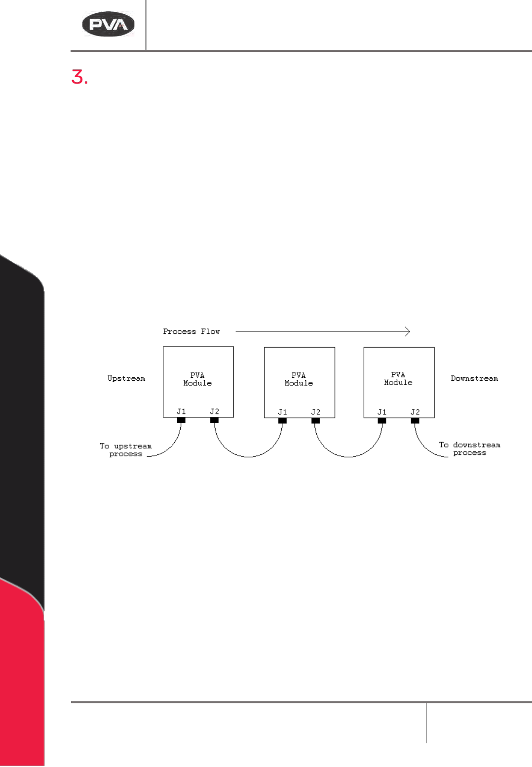
SMEMA cables have male 14-pin amp-type CPC connectors. The cables are straight-
through so orientation does not matter. On each module, the wire to the J1 plug must
connect to the J2 plug on the machine upstream. Similarly, the J2 plug on each machine
must connect to the J1 plug on the machine downstream, as shown below.
Figure 2: SMEMA Process Flow
DeltaTherm IR Cure Module
Revision B / February 2020
Page 11 of 41
Installation and Setup
WARNING: The following procedures should be done by qualified persons in
accordance with this manual and applicable safety regulations. A “qualified person”
is defined as “a person or persons who, by possession of a recognized degree or
certificate or professional training, or who, by extensive knowledge, training, and
experience, has successfully demonstrated the ability to solve problems relating to
the subject matter and work.” (ref. ANSI/ASME B30.2-1983.)
Installation
1. Plug the machine into an appropriate power source as shown on the legend plate on
the module. The electrical service should be correctly grounded and the power
source “clean”. If high power equipment operates off the same source, a line
conditioner may be necessary. Poor quality power can cause errors in machine
operation.
WARNING: Failure to obey electrical specifications can cause damage to the machine
or injury to installation personnel. Electrical hookup must be done by a qualified
electrician and must obey any applicable local standards.
2. Close any access doors and engage the EMERGENCY STOP button.
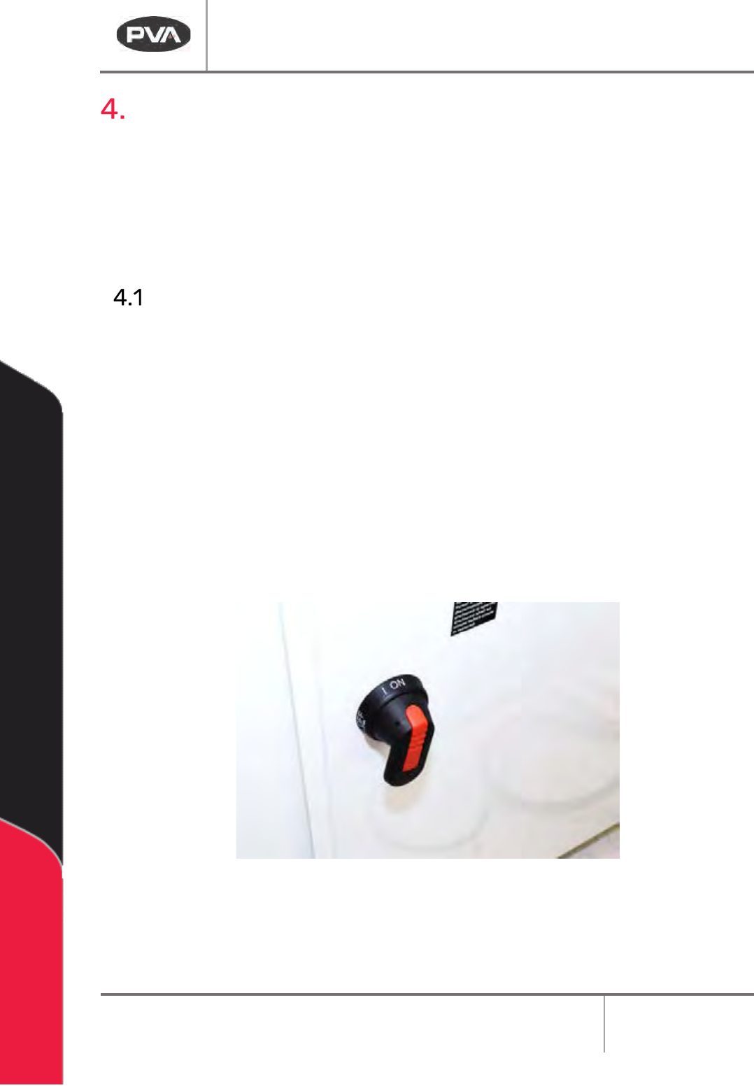
3. Turn the main power switch to “On”.
Figure 3: Power Switch "On"