DeltaTherm_IR_REV_B-1.pdf - 第14页
Delt aTherm IR Cure Modul e Revision B / February 2020 Page 14 of 41 Op eration Note : The screens shown in this manual are examples. However, the terminology used on the screens is consistent for all machines . ON/OFF o…
DeltaTherm IR Cure Module
Revision B / February 2020
Page 13 of 41
Exhaust Requirements
Exhaust
Requirement
Machine Duct Size
Air Velocity at Test
Point (ft/min)
Air Velocity at Test
Point (m/sec)
DeltaTherm 4’ 300 CFM 4” (102mm) 3438
DeltaTherm > 4’
600 CFM
6” (152mm)
3056
Note: Check machine specifications. Custom order machines and processes may require
higher exhaust flow rates.
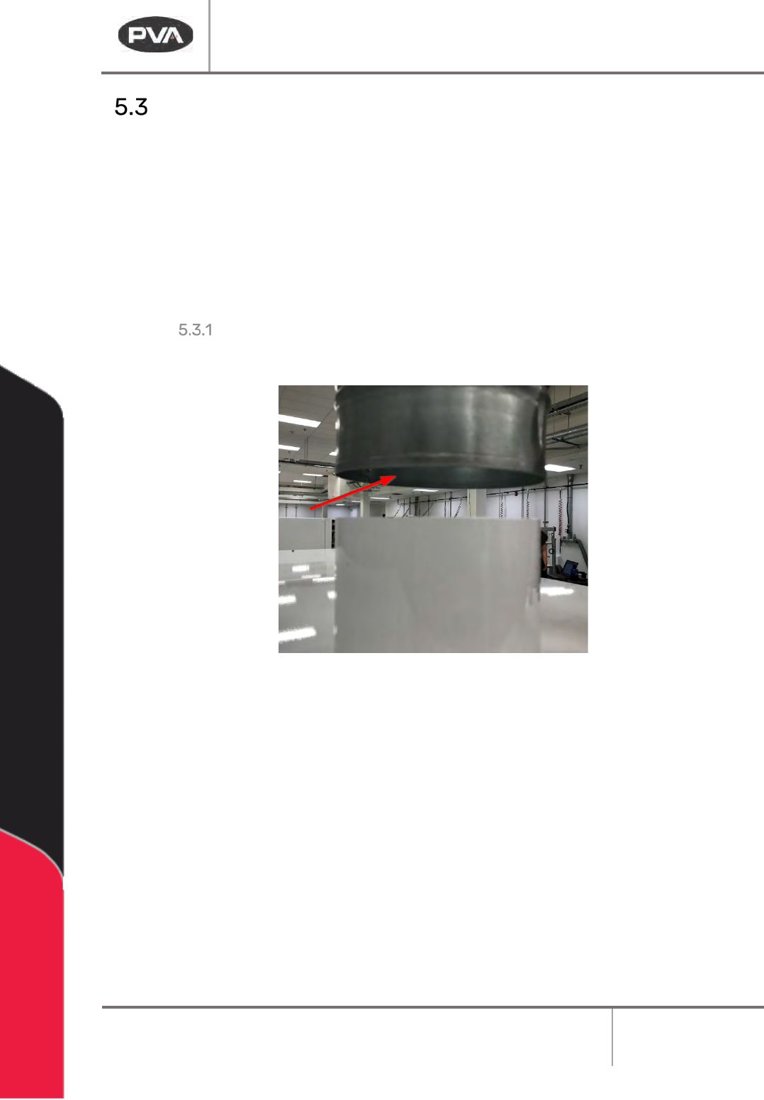
Air Velocity Test Point
Measure the velocity at the inlet to the factory supplied duct.
Figure 4: Air Velocity Test Point
DeltaTherm IR Cure Module
Revision B / February 2020
Page 14 of 41
Operation
Note: The screens shown in this manual are examples. However, the terminology
used on the screens is consistent for all machines. ON/OFF options are displayed by
showing black background with white lettering for ON and white background with
black lettering for OFF.
Startup Procedure
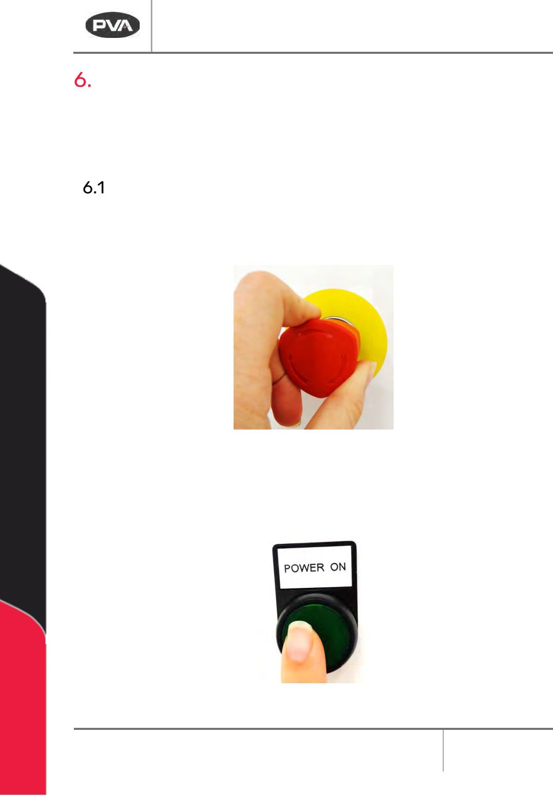
1. Close all doors.
2. Engage the EMERGENCY STOP button.
Figure 5: Emergency Stop Button
3. Turn the main power switch to ON.
4. Push the green POWER ON button on the front of the DeltaTherm module.
Figure 6: Power On Button
DeltaTherm IR Cure Module
Revision B / February 2020
Page 15 of 41
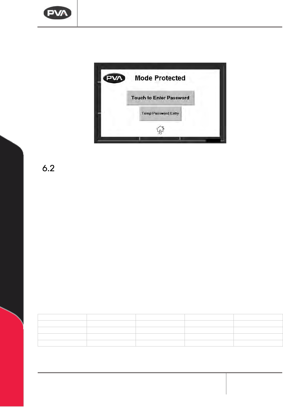
5. Enter your password as necessary, if in protected mode.
6. Operate the system as necessary.
Figure 7: Enter Password
Light Tower Operation
Three stacked indicator lights and a buzzer are used to show the machine status. The
lights are green, amber, and red. The buzzer is below the green light. The lights are visible
from all sides of the machine. The indicators operate as follows:
• The green light is on when the machine is in Auto Cycle and operates within
specified parameters. It is off at all other times.
• The amber light is on when the machine is in Auto Cycle but the specified
parameters have not been reached. It is off at all other times.
• The red light is on steady when the machine is not in Auto Cycle due to operator
intervention. It flashes when the machine is in cycle, but the cycle is stopped
because of a machine problem. It is off at all other times.
• The buzzer cycles when the red light flashes with machine errors. It also cycles
briefly when a board is at the end of the machine and must be unloaded (if the
offload alert option is selected in the Setup mode).
State
Red
Amber
Green
Buzzer
Cycle Stop
ON
OFF
OFF
OFF
Auto Cycle
OFF
ON
OFF
OFF
In Cycle
OFF
OFF
ON
OFF
Machine Error
FLASH
OFF
OFF
FLASH
Figure 8: Light Tower & Buzzer Status