DeltaTherm_IR_REV_B-1.pdf - 第23页
Delt aTherm IR Cure Modul e Revision B / February 2020 Page 23 of 41 Sens ors The PIP Sens ors c an be monitored in Manual mode for c orrect operat ion. Figure 16 : Senso rs in Manual M o de Note: Process PIP will only s…
DeltaTherm IR Cure Module
Revision B / February 2020
Page 22 of 41
The Conveyor Width can be set in Manual mode.
1. Press to manually enter the target conveyor width setpoint.
• Touch the screen and a keypad will be shown.
• Enter the necessary value.
• Push ‘ENT’, and the zone screen will be shown again.
2. Press to move the current target conveyor width setpoint.
Note: Prior to the move, the machine will check for any boards.
3. Press to rehome the conveyor width.
Note: Prior to the move, the machine will check for any boards.
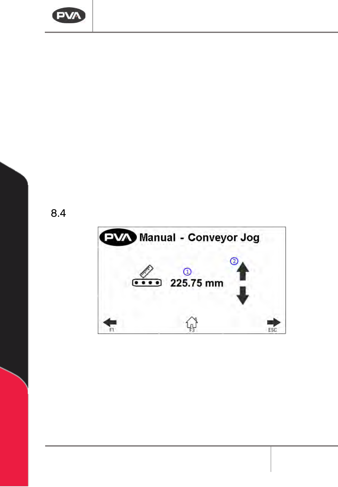
Conveyor Jog
Figure 15: Conveyor Jog in Manual Mode
1. This screen displays the current conveyor width.
2. Press to adjust the conveyor width. This will jog the conveyor width in a positive or
negative direction.
Note: The clearboard sequence will not run prior to the jog.
DeltaTherm IR Cure Module
Revision B / February 2020
Page 23 of 41
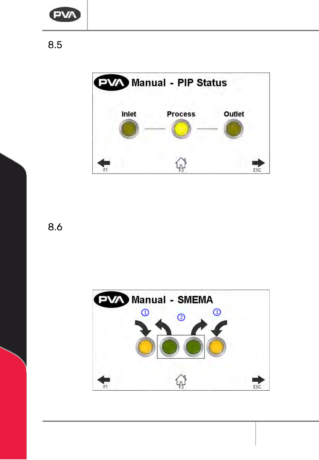
Sensors
The PIP Sensors can be monitored in Manual mode for correct operation.
Figure 16: Sensors in Manual Mode
Note: Process PIP will only show on 12 ft and 16 ft oven length systems.
SMEMA Control
1. The SMEMA inputs (Upstream Board Available and Downstream Ready) can be
monitored for correct operation through the SMEMA screen in Manual mode.
2. Select the necessary output (Machine Ready and Board Available) to toggle it on or
off.
Figure 17: SMEMA in Manual Mode
DeltaTherm IR Cure Module
Revision B / February 2020
Page 24 of 41
Setup Mode
In Setup mode, the operator can set basic functions of the machine and Auto Cycle
parameters. These parameters (depending on the machine) are the current recipe, IR panel
temperatures, allowable deviations, conveyor width, and conveyor speed. Parameters are
saved in the controller under the current recipe even when the module is shut down. Push
the Home button or the F3 button at any time to exit Setup mode and return to cycle stop.
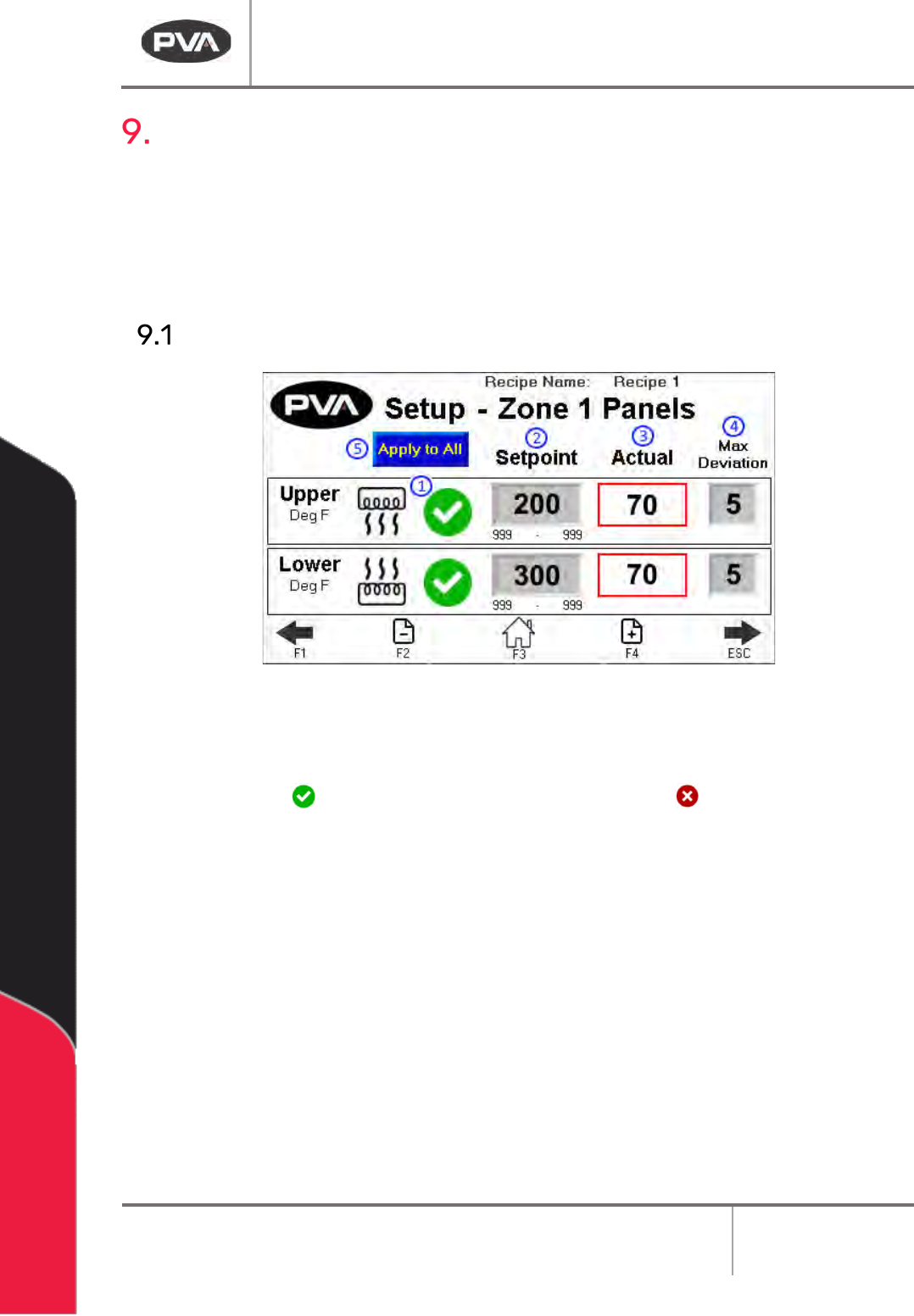
IR Panels
Figure 18: Setup Zone 1 Panels
1. The Heater Panel Recipe Switch can disable or enable the use of a zone’s upper or
lower heater panel in Autocycle. If enabled, the panel will display a green
checkmark . If disabled, the panel will display a red X .
Note: IR panels cannot activate unless the exhaust fan is on.
2. The Setpoint box is the target temperature (display temperature is filtered) for
each zone and the deviation box is the permitted deviation from the setpoint for
that zone.
• Touch the Setpoint box and a keypad will be shown.
• Enter the necessary value. The system minimum and maximum are shown
below the numeric field.
• Press “ENT” to save the value and close the keypad.