KE2040 Instruction Manual_ver1.30.pdf - 第384页
5 − 42 ⑱ Exp (Expansion) Set this item f or an extended- lead connector , or unidirectional connect or . - W hen you click this item with the rig ht butt on, the select ion pop-up menu appears on the screen. ▼ W hen you …
5 − 41
2) Number of leads to be recognized
Enter the number of leads at each corner to be recognized. See the
conditions for entering the number of leads shown in Table 5.2.3.16 below.
Table 5.2.3.16.1 Range of the number of leads
Range of the number of leads
Component type Recognition pattern
Upper
left
corner
Upper
right
corner
Lower
left
corner
Lower
right
corner
Unidirectional
connector
All
Only the both ends lead
Both ends lead exclusion
****
1-3
0-3
****
1-3
0-3
****
****
****
****
****
****
Bidirectional
connector
Z-shaped lead
connector
All
Only the both ends lead
Both ends lead exclusion
****
1-3
0-3
****
1-3
0-3
****
1-3
0-3
****
1-3
0-3
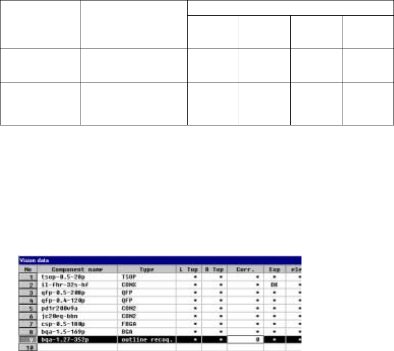
⑰ Corr.(Brightness correction)
Set the threshold to be applied when the machine recognizes an
outline-recognized component.
- “0” is set as the initial value. If the machine cannot recognize such a
component, adjust the initial value between – 127 and + 127. When a
component looks darker, set the smaller number. When you can see even
the background of a component, increase the value.
5 − 42
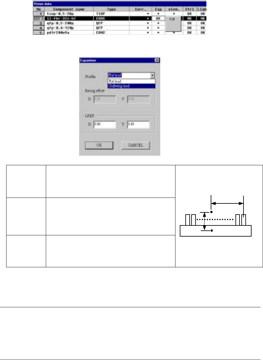
⑱ Exp (Expansion)
Set this item for an extended-lead connector, or unidirectional connector.
- When you click this item with the right button, the selection pop-up menu
appears on the screen.
▼ When you click the [Edit] command, the following screen appears.
Profile Set the shape of a lead.
- Flat lead
- Gullwing lead
By default, “Gullwing lead” is selected.
Recog offset
(Recognition
offset)
Displays the recognition center offset which was set on
the “Expansion” window invoked from the Component
data screen. You cannot edit any of these values on
this screen. This item shows the coordinates of the
lead center A with being viewed from the component
pick-up position C.
LREP.
(Rightmost
lead position)
Enter the coordinates of the rightmost lead position:
coordinates of the rightmost lead center B with being
viewed from the lead center A. The default value is
determined based on the lead pitch and number of
leads.
♦ When you finish entering all of data, click the <OK> button. The “Vision
data” screen reappears.
Notes:
①
The machine cannot recognize images of an extended-lead connector with
dividing it.
②
Note that only one point, the rightmost lead position is set on this screen, so
the recognition precision is insufficient.
C
CC
C
A
AA
A
B
BB
B
5 − 43
5.2.4 General-purpose vision components
5.2.4.1 Overview of a general-purpose vision component
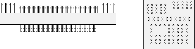
The following types of components are handled as a general-purpose vision
component (“GNRL. vision” displayed as the component type):
- Components having multi-pitch leads, components having various sized leads,
and components having leads at not-regulated positions (these components are
called “multi-lead” components; see Figure -1.)
- Area array components having two or more arrays (called “complex array
components”; see Figure -2.)
- Components having balls/lands on not-regulated positions (called “random
component”)
- Components having a side or corner (outline-recognized components)
• The components above are classified into the following sub-component types:
Multi-lead component: Lead component group
Complex array component and random component: Ball component
group
Outline-recognized component: Outline-recognized component group
• The data format definition of each type of components is as follows:
Multi-lead component, complex array component and outline-recognized
component → Element group/Element format
Random component → Extended array data format
* The “Element group/Element format” specifies an element to be recognized such
as a lead and ball, defines the group of the same elements (element group): the
pitch and/or quantity is the same, and specifies the direction and position of the
group.
The “Extended array data format” defines the element (ball and land) arrangement
with X and Y coordinates.
Figure -1 Figure -2
Ball component group
(Complex array component)
Lead component group (Multi-lead component)