KE2040 Instruction Manual_ver1.30.pdf - 第629页
8 − 38 8.2.2.12 PWB convey or A screen appears as shown in Figure 8.2. 2.12.1 “ PW B conv eyor setting dialog box” when [PW B conveyor] is selected f rom t he [Setting Group] menu. Figure 8.2. 2.12.1 PWB convey or setti …
8 − 37
8.2.2.11 Multi-station line
A screen appears as shown in Figure 8.2.2.11.1 “Multi-station line setting dialog
box” when [Multi-station line] is selected from the [Setting Group] menu.
Figure 8.2.2.11.1 Multi-station line setting dialog box
(1) Setting items
No. Item Description
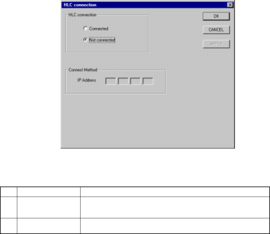
1 HLC connection This command is used to define whether or not this machine is connected to
an HLC in a multi-station line where two or more general purpose placers,
chip placers and bonding machines are connected to the HLC.
2 IP address Since the HLC and each station are to be communicated with each another
via the network, an IP address needs to be defined for each station.
(2) Setting the Multi-station line
① Connection to the HLC
− Using the radio button, define whether or not the machine is to be
connected to the HLC. (Default setting: Not connected)
② Connecting method (IP address)
− Each field of an IP address can be any number from 0 to 255. Two or
more stations cannot have the same IP address. Note that you cannot
set all fields to “0”.
− An IP address is a fixed number for the HLC.
− When “Connected” is selected with the “HLC connection” radio button,
set each field of an IP address to a value from 0 to 255. This dialog
cannot be closed when a number out of that range is set.
8 − 38
8.2.2.12 PWB conveyor
A screen appears as shown in Figure 8.2.2.12.1 “PWB conveyor setting dialog box”
when [PWB conveyor] is selected from the [Setting Group] menu.
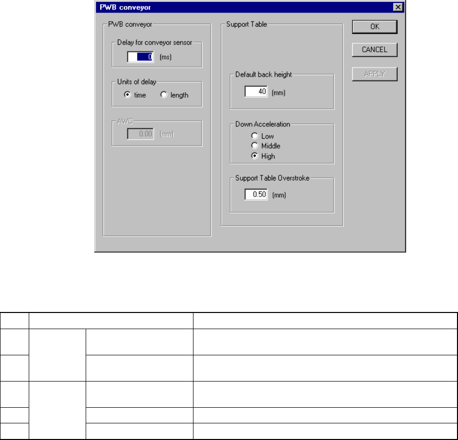
Figure 8.2.2.12.1 PWB conveyor setting dialog box
(1) Setting items
No. Item Description
1 Delay for conveyor
sensor
Sets the delay time or distance of the board conveyor sensor
for a cut out board or punch hole board.
2
PWB
Conveyor
Units of delay Sets the unit used for the delay of the board conveyor sensor
specified with the item “Delay for PWB conveyor sensor”.
3 Under Limit for
conveyor
Sets the PWB position lower limit on the backup table.
4 Down Acceleration Sets the acceleration of the backup table.
5
Back Up
Table
Press In Sets the stroke pressure of the backup table.
(2) How to set
① Delay for conveyor sensor
− This can be set in the range from 0 to 1000.
As a guide, set "60 ms" for a cut out board.
② Units of delay
− With using the radio button, select the unit for delay.
− When you select “time”, the value you selected with the item “Delay for
conveyor sensor” is handled as the “delay time” in the unit of ms.
− When you select “length”, the value you selected with the item “Delay
for conveyor sensor” is handled as the “delay distance” in the unit of
mm.

8 − 39
Note: When you change the setting of this "Units of delay", the setting of the item
①
"Delay for conveyor sensor" is cleared.
③ Under Limit for conveyor
− Specify the value in the range from 5 to 30 (Unit is fixed to mm.).
④ Down Acceleration
− With using the radio button, set one of three steps: Low, Medium, and
High (default setting: High).
⑤ Press In
− Specify the value in the range from 0.00 to 5.00.