KE2040 Instruction Manual_ver1.30.pdf - 第814页
13 − 32 (4) Measurable Rang e T he measurable rang e of a lead is 1 mm or less. If the area indicat ed below exceeds this range, an er ror occurs. Figure 13.12.3. 1 M easurable range (5) Par ameter s to be entered f or m…
13 − 31
13.12.3 Overview of the specifications
(1) Applicable components
QFP and SOP
Only if they are recognized by the VCS.
(2) Resolution and precision
①
Resolution: 1μm
②
Precision: ±20 μm (when measured with a JUKI standard gauge)
L
This device may not correctly judge a component whose terminal is
damaged due to contact with contact probe.
(3) Measurement mode and dimensions of a component
Two measurement modes are provided: Standard mode and High-Precision
mode.
In Standard mode, the device scans a component at 80 mm/s with the sensor,
while in High-Precision mode, it scans a component at 20 mm/s.
◇ Specifications of a component that can be measured in each mode are
shown below:
Table 13.12.1 Dimensions of a component in each mode
Item Standard mode High-Precision mode
Pitch 0.4 mm or more 0.3 mm or more
Lead width 0.18 mm or more 0.12 mm or more
Lead length 0.3 mm or more 0.3 mm or more
Batch
measurement
26 mm x 100 mm or less 26 mm x 50 mm or less
Lead
components
Component
size
Division
measurement
50 mm x 100 mm or less 50 mm x 50 mm or less
◆
When you switch a measurement mode between Standard mode and
High-Precision mode, it takes three seconds to switch the rotating
speed of the polygon mirror. Therefore, if you are to produce both
components that should be measured in Standard mode and those
that should be in High-Precision mode, the production cycle time
becomes longer.
◆
The length of a gull-wing lead indicates that of a lead located on the
foot section.
◆
Component height
* [If the dimensions of a component exceed those above, the
maximum component height should be 8 mm.]
Model name KE-2020 KE-2040
Component height (Maximum) 12mm 20mm 25mm
Note that the value described above is applied to a component when its longer side is 50 mm or shorter, and
the shorter side is 45 mm or shorter.
L
13 − 32
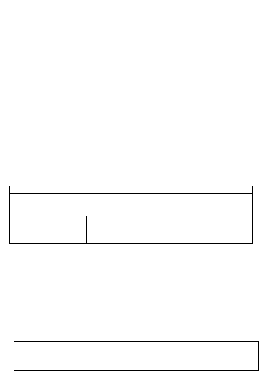
(4) Measurable Range
The measurable range of a lead is 1 mm or less. If the area indicated below
exceeds this range, an error occurs.
Figure 13.12.3.1 Measurable range
(5) Parameters to be entered for measurement
①
Tolerance: Coplanarity judgment value to be used for measurement
②
Electrode size: width and length
③
Lead Gloss: information on how glossy a lead is, Normal, Shiny and Dull.
④
Lead Brightness Threshold
⑤
Laser Strength: 0 to 7
⑥
Measurement Height Offset
⑦
Scanning Offset (Measurement position viewed form a tip of a lead)
⑧
AGC Adjustment: 0 to 5
⑨
Measurement Mode
(6) Output of measurement result
①
Judgment: if the result is good or bad with comparing to the preset
judgment value.
②
Information on height of all terminals and judgment
(7) Laser strength
Laser: Class 1 (JISC6802, IEC60825-1)
850 mm infrared semiconductor laser (invisible light)
1mm
13 − 33
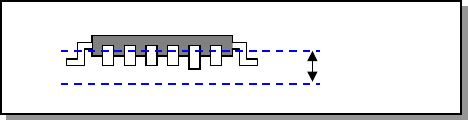
13.12.4 Operations
To perform coplanarity check, start up the Setup utility from the main screen, and
make settings on each screen invoked from the Setup utility.
Figure 13.12.4.1 Main screen
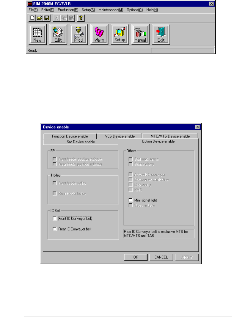
13.12.4.1 Machine setup
Select the [Setup] command from the menu bar, and the [Machine Setup], [Setup],
and [Device enable] commands in this order.
(For details, see Section 8.2.2.10.2 “Option Device enable” of Chapter 8 “MACHINE
SETUP”.)
Figure 13.12.4.2 Device enable dialog box
½ Check to see if the check box “Coplanarity” provided as the “Others” menu item is
checked.
;
When you make all of the necessary settings, click the <OK> button. If you
do not have to make/change any setting, click the <CANCEL> button.
☞