KE2040 Instruction Manual_ver1.30.pdf - 第395页
5 − 53 5.2.4.4 Procedure for creating general-purpose vision component dat a 5.2.4.4. 1 Lead components (Element group/ Element format ) This section describes t he procedure f or creat ing data on lead com ponents (mult…
5 − 52
L
LL
L
W
WW
W
L
LL
L
W
WW
W
L
LL
L
W
WW
W
Setting item Description
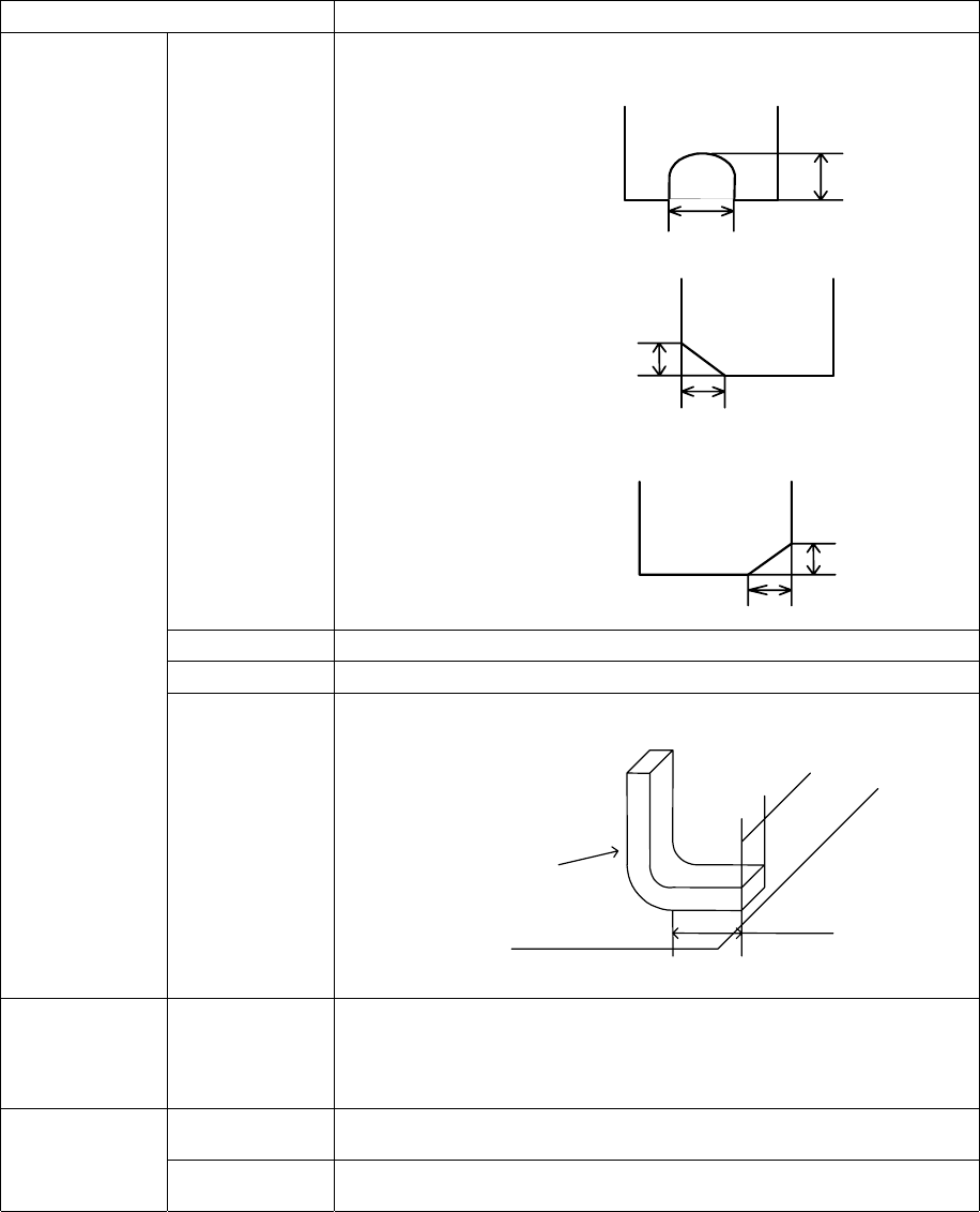
Cut shape Select a cut shape of a lead:
- Flat
- U-shape cut
- Cut at the lower left corner
- Cut at the lower right corner
Cut length Enter the length of a cut portion of a lead (L).
Cut width Enter the width of a cut portion of a lead (W).
Lead size Enter the length and width of a foot portion of a lead.
Ball/Land/Column Inspection
(Diameter, Area,
Ball exist? And
Average
diameter)
Set whether to check a ball/land/column and the reference level.
OK Registers data and displays the “Element Group” or “Extended Array” screen
again.
Cancel Cancels data registering and displays the “Element Group” or “Extended Array”
screen again.
Length
Width
Lead
Board
5 − 53
5.2.4.4 Procedure for creating general-purpose vision component data
5.2.4.4.1 Lead components (Element group/Element format)
This section describes the procedure for creating data on lead components
(multi-lead components).
1) Operation on the “Extended Vision” screen
- Select “Lead Component” on the “Component Type” combo box.
- Check the “Element group/Element format” check box in the “Define data
format” field.
- Click the <Add> button on the “Element Group List”.
2) Operation on the “Element Group” screen
Define an element group on this screen.
An element group is composed of components whose lead size and pitch are the
same.
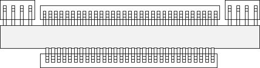
See Figure 5.2.4.4.1 for an example of a multi-lead component. The procedure
for creating data on this component is to be described below.
▼
▼▼
▼ Description
In the example below, four element groups are defined. The size and pitch of
leads of the first and third element groups are the same, while the direction and
position of leads of these groups are different from each another. The size and
pitch of leads of the second and fourth element groups are the same also, but
leads of these groups are not arrange continuously, so the lead pitch is not the
same. If the distance between these leads is an integral multiple of the specified
pitch, they can be defined as one element group that has an area having no lead.
However, we recommend that you define them as separate element groups.
To define the direction and position of the element group, specify the component
posture. In Figure 5.2.4.1.1, the direction of a component shown is normal. The
posture of multi-lead components is regulated from the top view.
Figure 5.2.4.4.1
Fourth element
group
Third element
group
Second
element group
First element
group
Top View
5 − 54
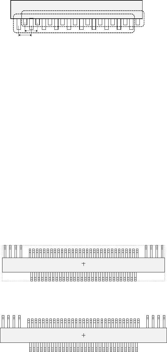
If the length of a lead changes alternatively as shown in Figure 5.2.4.4.2, define
two groups: one having long leads and another having short leads. The pitch is
also defined for a group of long leads and that of short leads separately.
Figure 5.2.4.4.2
① Name
Name an element group to be handled. When you want to change an
element group, specify its name to edit it.
- A name is assigned automatically with serial numbers.
- Users can change this numbered name to an alphanumeric name (up to 32
characters).
In the example, the numbered name is used.
② First element position
Specify the position (X, Y) and direction (Theta) of an element group.
As the position, specify the distance (offset) from the center of a component.
Normally, the center of a component is the center of the component outline.
- If the placement coordinates set in Placement data of a production program
is not based on the center of the component outline, you can specify the
coordinates of the reference component center with coordinates different
from the center of the component outline.
Figure 5.2.4.4.3 indicates that the center of the component outline is the
center of a component, while Figure 5.2.4.4.4 indicates that the center of
component body is the center of a component.
Figure 5.2.4.4.3
Figure 5.2.4.4.4
Top View
Center of a component
(Center of the component outline)
Top View
Center of a component
(Center of the component body)
Second element group
First element group
Pitch 2
Pitch 1