KE2040 Instruction Manual_ver1.30.pdf - 第820页
13 − 38 13.12.8 Error processing W hen the device detects an error as the r esult of coplanarity check, the system displays an error log when it does not place an er ror com ponent on a board. Figure 13.12.8. 1 Error dia…
13 − 37
13.12.7 Production
The system performs a coplanarity check during production, trial run or blank-run.
L
* The system does not perform a coplanarity check actually during blank-run.
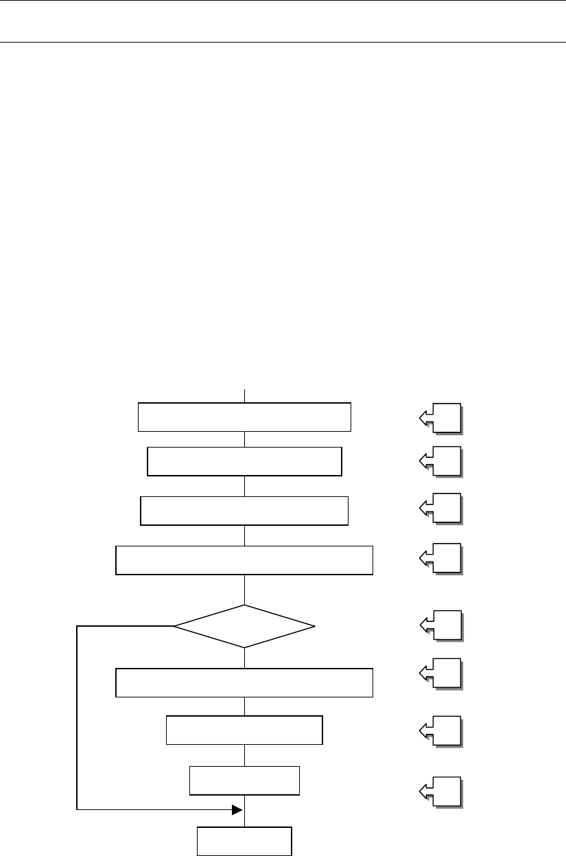
13.12.7.1 Procedure for coplanarity check
① Picking of a target component
② Moving to the VCS position
③ Recognition of the target component vision by the VCS
④ Moving to the coplanarity sensor measurement start position
⑤ Checking if the device can perform a coplanarity check for the target component
⑥ Correction of the position based on the result of vision recognition
⑦ Performing coplanarity check for the component
⑧ Judging if the target component passes the check based on the result of
measurement by the coplanarity sensor
[Process after judgment]
8_1 Discarding the component
8_2 Placing the component
8_3 Pause
Figure 13.12.7 Process flow chart
Moving to the VCS position
①
②
③
④
⑤
⑥
⑦
⑧
Picking of the target component
Vision recognition by the VCS
Moving to the coplanarity sensor position
Correction of the component position
Coplanarity check
Judgment
End
Checking the
com
p
onent
13 − 38
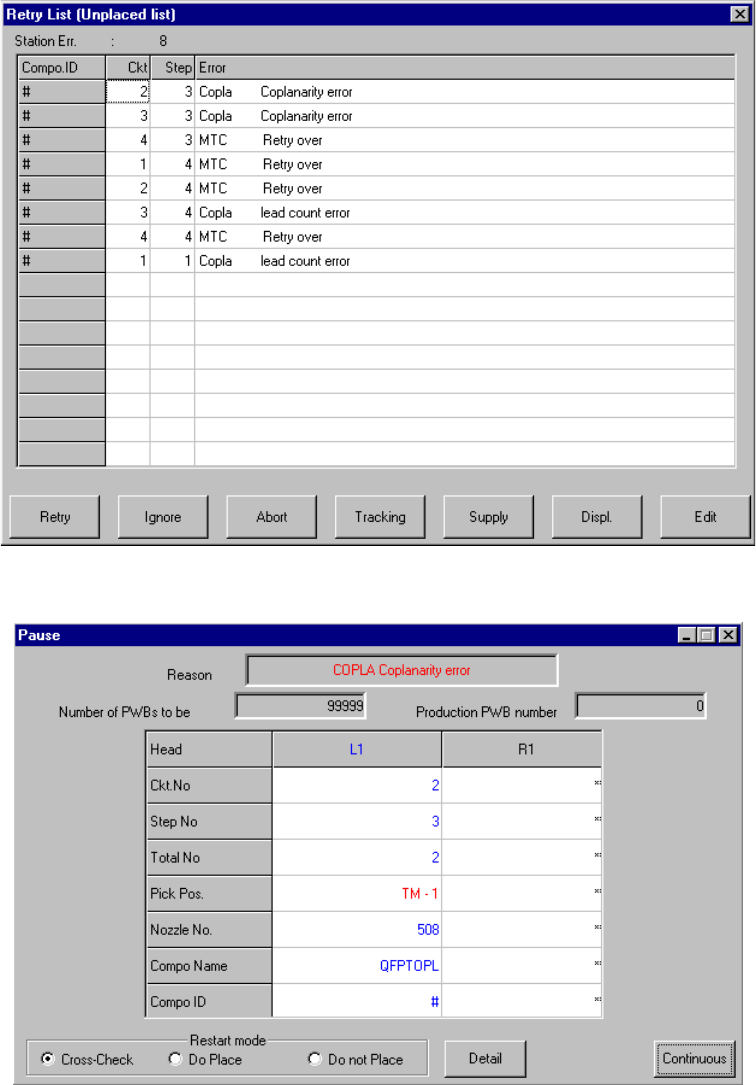
13.12.8 Error processing
When the device detects an error as the result of coplanarity check, the system
displays an error log when it does not place an error component on a board.
Figure 13.12.8.1 Error dialog box
Figure 13.12.8.2 Pause dialog box
13 − 39
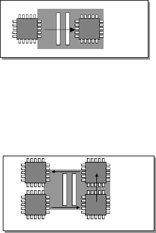
13.12.9 Overview of the coplanarity check operation
Movements of a component over the axis sensor during coplanarity check are
described below.
13.12.9.1 Batch component check
The device scans a component whose size is specified for “Batch measurement” in
(3) Measurement mode and dimensions of a component of Section 13.12.3 in a single
direction to measure it.
13.12.9.1 Batch measurement operation
13.12.9.2 Division component check
The device scans a components whose size is specified for “Division measurement”
in (3) Measurement mode and dimensions of a component of Section 13.12.3 as
shown in Figure below to measure it.
Figure 13.12.9.2 Division measurement operation